144 Rockwell Automation Publication 2080-UM002L-EN-E - November 2021
Chapter 8 Use the High-Speed Counter and Programmable Limit Switch
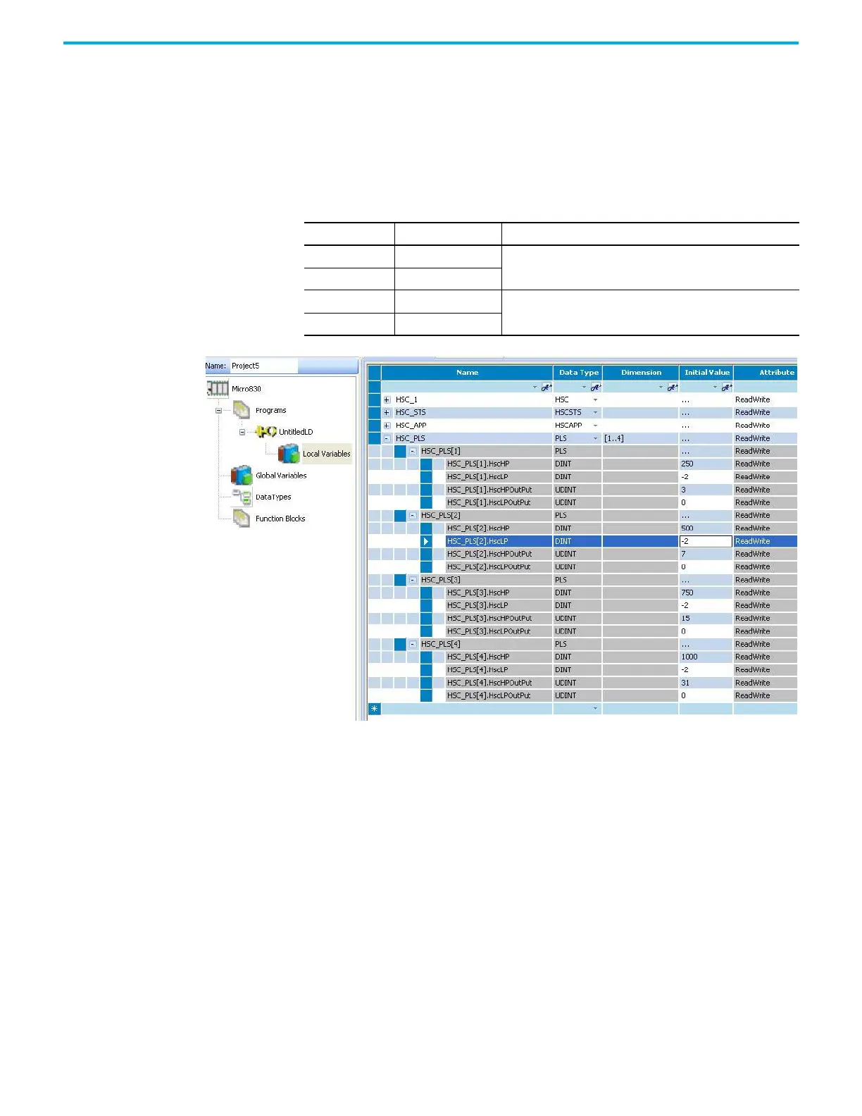
PLS Example
Setting Up the PLS Data
Using Connected Components Workbench software, define the PLS data
HSC_PLS’s dimension as [1…4].
Once the values above for all 4 PLS data elements have been entered, the PLS is
configured.
Assume that HSCAPP.OutputMask = 31 (HSC mechanism controls Embedded
Output 0...4 only), and HSCAPP.HSCMode = 0.
PLS Operation for This Example
When the ladder logic first runs, HSCSTS.Accumulator = 1, therefore all the
outputs are turned off. The value of HSCSTS.HP = 250
When HSCSTS.Accumulator = 250, the HSC_PLS[1].HscHPOutput is sent
through the HSCAPP.OutputMask and energizes the outputs 0 and 1.
This will repeat as the HSCSTS.Accumulator reaches 500, 750, and 1000. The
controller energizes outputs 0...2, 0...3, and 0...4 respectively. Once completed,
the cycle resets and repeats from HSCSTS.HP = 250.
PLS Data Definition
Data Description Data Format
HSCHP High Preset
32 bit signed integer
HSCLP Low Preset
HSCHPOutput Output High Data
32 bit binary
(bit 31--> 0000 0000 0000 0000 0000 0000 0000 0000 <--bit 0)
HSCLPOutput Output Low Data

 Loading...


