30
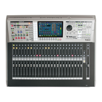
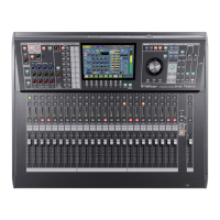
Explanation of the panels
Explanation of the panels
fig.ConsInJackGuide.eps
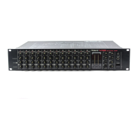
These are balanced XLR-3-31 female input jacks for inputting
analog audio signals from microphones or line level equipment.
By default they are patched to CH33–40.
922
Wiring diagrams for these jacks are shown below. Make
connections after first checking the wiring diagrams of other
equipment you intend to connect.
fig.XLRJackInput.eps
926a
When connection cables with resistors are used, the volume
level of equipment connected to the inputs (CONSOLE
INPUT jacks, TALKBACK MIC IN jack, or STEREO IN jacks) may
be low. If this happens, use connection cables that do not
contain resistors.
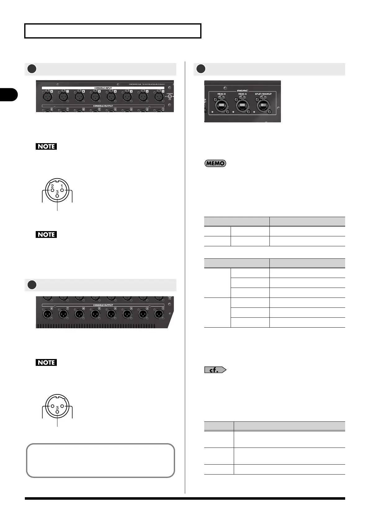
fig.ConsOutJackGuide.eps
These are balanced XLR-3-32 male output jacks for outputting
analog audio signals. By default, AUX OUT 1–8, MONITOR L/R are
patched to them.
922
Wiring diagrams for these jacks are shown below. Make
connections after first checking the wiring diagrams of other
equipment you intend to connect.
fig.XLRJack.eps
fig.REACPortGuide.eps
• REAC A, B port
These are RJ45 connectors for connecting input/output units
such as the S-1608, S-0816, or S-4000S via Cat5e Ethernet
cables.
These connectors support Cat5e Ethernet cables up to 100
meters long. If you need a longer connection, we recommend
that you use the optional S-OPT.
The default input/output patching between the M-480 and
input/output units connected to REAC ports A/B is as
follows:
• SPLIT/BACKUP port
This is used as a backup connection for the REAC A port, or
for split connection. You can also use it for multi-channel
recording on a PC in which you’ve installed the REAC driver.
For details on backup connections and slit connections, refer to
“REAC applications and settings” (p. 142).
The REAC A/B ports and SPLIT/BACKUP port have REAC
indicators that show the REAC communication status. The
state of the REAC indicator has the following significance:
CONSOLE INPUT jacks
CONSOLE OUTPUT jacks
1
+PHANTOM [+48V/14mA]
GND
COLD
HOT
2
HOT
COLD
GND
12
The CONSOLE INPUT 1–8 jacks and CONSOLE OUTPUT 1–8
jacks can also be used as input/output jacks for inserting
external effect processors into channels. For details, refer to
“Inserting an external effects device” (p. 110).
REAC ports (A, B, SPLIT/BACKUP)
Input jacks
Input channel
REAC A
IN1–16 CH1–16
REAC B IN1–16 CH17–32
Output jacks
Outputs
REAC A
OUT1–6 AUX1–6
OUT7–8 MAIN L, R
OUT9–40 CH1–32 DIRECT OUTS
REAC B OUT1–6 AUX9–14
OUT7–8 MAIN L, R
OUT9–40 CH1–32 DIRECT OUTS
Status Explanation
Unlit
No connection with a REAC device has been
established.
Lit
A split connection with a REAC device has been
established.
Blinking Connected normally with a REAC device.
M-480_e.book 30 ページ 2011年3月2日 水曜日 午前9時20分
 Loading...