80
Dynamics
Dynamics
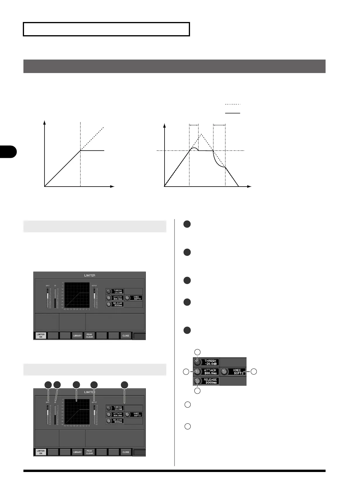
Limiters are provided on each AUX1–
16
, MTX1–
8
, and MAIN L/R/C.
They attenuate the signal so that the output does not exceed the threshold level.
fig.LimCurve.eps
The LIMITER popup is used to perform limiter operations.
Limiter operations
INPUT LEVEL TIME
OUTPUT LEVEL
LEVEL
THRESHOLD
THRESHOLD
ATTACK
RELEASE
INPUT SIGNAL
OUTPUT SIGNAL
(KNEE=HARD)
1.
In the fader module section, press [SEL] to select the
desired channel.
2.
In the COMP area of the CHANNEL EDIT section, press
[DISP].
fig.PopLmt.eps
The LIMITER popup will appear.
fig.PopLmtGuide.eps
IN meter
This indicates the input level of the limiter. For stereo-linked
channels, two meters (L and R) are shown.
GR (Gain reduction) meter
This indicates the amount of gain reduction produced by the
limiter.
Limiter graph
This indicates the approximate response of the limiter.
OUT meter
This indicates the output level of the limiter. For stereo-
linked channels, two meters (L and R) are shown.
Parameters
In this field you can edit the compressor parameters.
fig.PopLmtGuide2.eps
THRESH knob
This adjusts the threshold level in a range of -40.0 dB–0.0 dB.
ATTACK knob
This adjusts the ATTACK time in a range of 0.0 ms–800.0 ms.
This is the time from when the input signal exceeds the
threshold level until the limiter reaches its maximum effect.
Accessing the LIMITER popup
LIMITER popup
2
1
3
4 5
1
2
3
4
5
1
2
3
4
1
2
M-480_e.book 80 ページ 2011年3月2日 水曜日 午前9時20分
 Loading...