91
Input/output patchbay
Input/output patchbay
By using the cascade outputs in the output patchbay, and the
cascade inputs in the input patchbay, you can connect the AUX
buses, MTX buses, or MAIN buses between two or more M-480s.
This enables the number of input channels to be greatly
increased.
If you cascade-connect the M-480 using a REAC connection, you
can link a variety of functions by using the Cascade Link function
(p. 92).
fig.CascadeDia.eps
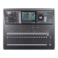
From the cascade outputs of one M-480, the bus signals for the
cascade-connection flow into the cascade inputs of another M-
480. The M-480 on the upper-side of the signal flow is called
“Cascade Slave” console, and the last one of the signal flow is
called “Cascade Master” console. The cascade connected bus can
be outputted from the Cascade Master console.
fig.Cascade_Slave_Master.eps
* If you use the M-480’s SPLIT/BACKUP port (p. 30) for the cascade
connection, it is not possible to use the Cascade Link function (p. 92).
* CAS OUT MAIN L, R, C does not contain the signal sent from the AUX.
* CAS OUT MTX 1–8 does not contain the signal sent from the AUX or
MAIN.
* The attenuator for the AUX, MTX, or MAIN acts when input signals are
summing into the bus. When you use the attenuator for AUX, MTX, or
MAIN, you have to adjust it for each of the M-480s.
* When REAC is used for the cascade connection, the word clock
worsens as the number of M-480 increase. Noise may occur when you
cascade connect more than two M-480s using REAC.
* Because of the mixing latency and input/output latency (REAC, Analog
Audio, or AES/EBU), the cascade output signals from one M-480 are
mixed into the other M-480’s buses with a minimal delay. Compensate
for this delay by using the input channel delay. In this case, all signals
for cascade-connection should go through same route so that the
delay time for all cascade signals will be same (e.g. all signals
connected via REAC.)
Cascade connection
Signal flow
MAIN
LRC LR
SOLOAUX
12 1615
MAIN
LRC LR
SOLOAUX
1 2 15 16
MTX
12 78
MTX
12 78
Link to BUS ATT, SOLO LEVEL
OUTPUT
PATCHBAY
CASCADE OUTPUT
AT T
AT T
AT T
LEVEL
MAIN L, R, C
AUX 1–16
MTX 1–8
SOLO L, R
MAIN L, R, C
AUX 1–16
MTX 1–8
SOLO L, R
INPUT
PATCHBAY
CASCADE INPUT
Cascade Slave
Cascade
Outputs
Inputs
Cascade
Inputs
Cascade Master
Inputs Outputs
Notes when using cascade-connection
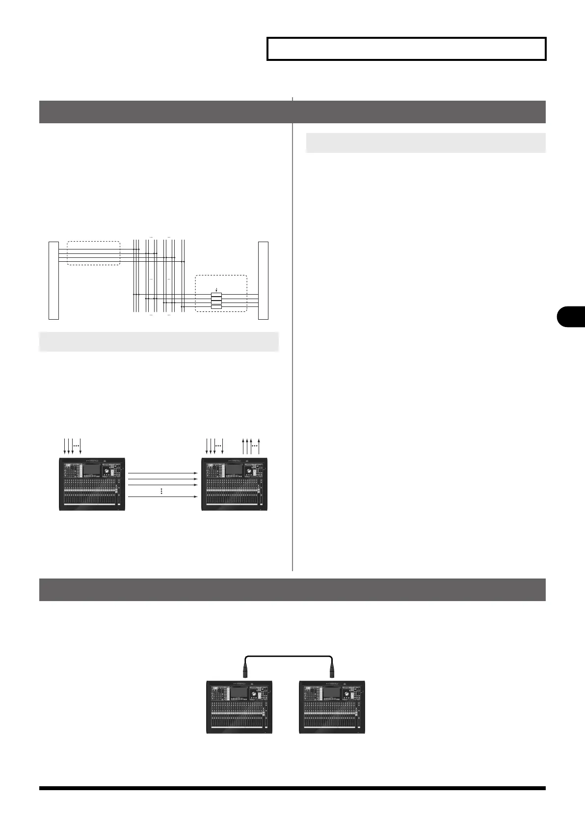
Setting up Cascade connection
Here we explain how to setup the cascade connection by giving the example of two M-480 cascaded using the REAC B of the Cascade
Slave console and the REAC A of the Cascade Master console.
fig.Cascade_Example.eps
Cascade Slave
REAC B REAC A
MASTER SPLIT
Cascade Master
M-480_e.book 91 ページ 2011年3月2日 水曜日 午前9時20分
 Loading...