16-3
OP27,
OP37 Equipment Manual
Release 05/99
16.3 Connection Elements
Ê
ËÌ
ÎÏ Ð
Ñ
Ò
Í
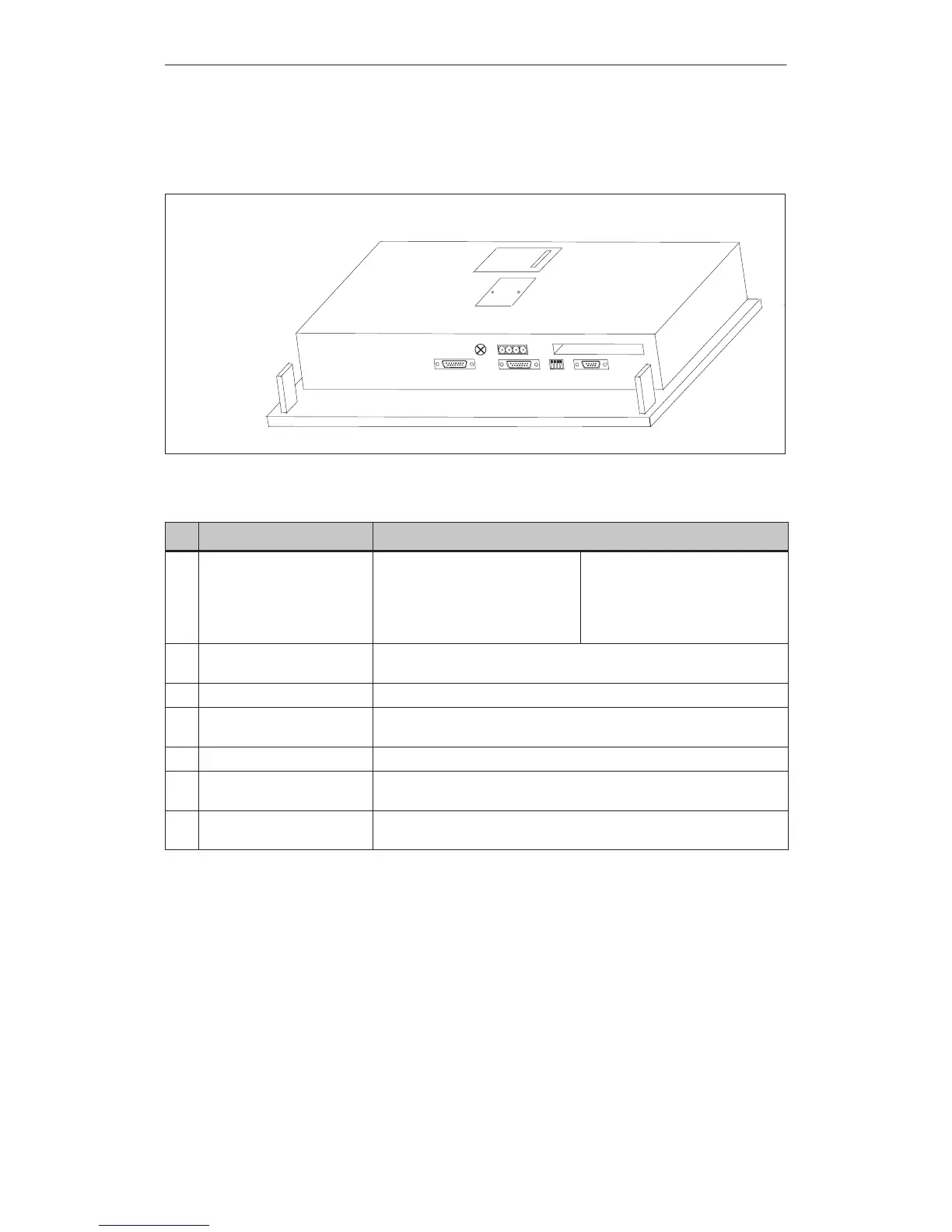
Figure 16-2 OP27: Arrangement of connections
No. Name/Purpose Description
Serial interfaces
1)
: Level Usage
Ê IF1A RS232/TTY (active/passive) PLC
Ë IF2 RS232/TTY (active/passive) PC, PU, printer
Í IF1B RS422/RS485 PLC
Ì DIL switch For setting serial interface IF1B (refer to Appendix B). Set and check with
the table in Section 13.1.2, Configuring the IF1B interface.
Î Chassis ground –
Ï Power supply/relay output Power supply (+ 24 V DC) and contact assemblies
(For pin assignment, refer to Section 13.1).
Ð PCMCIA slot For JEIDA/PCMCIA cards.
Ñ DKM or CPI (optional) For connecting a direct key module with 8 digital outputs or a control panel
interface with max. 16/32 digital inputs/outputs.
Ò Battery compartment
(covered)
–
1) The
connection plug pin assignment is described in Appendix B.
OP27
Unit Description
Artisan Technology Group - Quality Instrumentation ... Guaranteed | (888) 88-SOURCE | www.artisantg.com
 Loading...