18-7
OP27,
OP37 Equipment Manual
Release 05/99
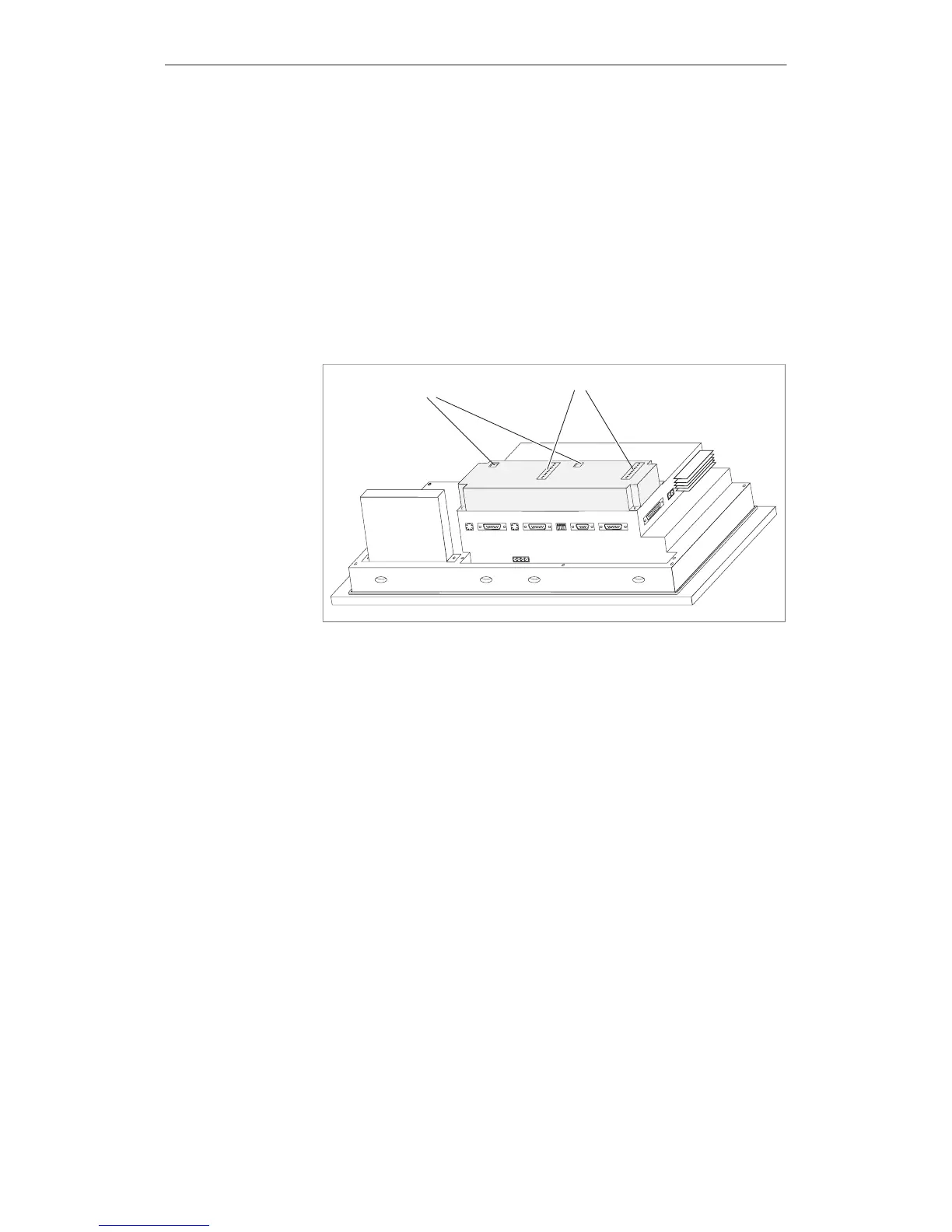
18.2.2 Connection and Adjusting Elements
Each
module has
a 10-pin plug connector
for connecting the outputs and the external power supply
a DIL switch
for defining whether the outputs are determined by the stroke of a key or by
software.
When installed, the plug connector and the DIL switch are located on the rear
panel of the OP
.
DIL switch
Pins
DKM A
DKM B
Figure 18-7 Location of connection and adjustment elements on large module housing
(example OP37)
Options
Artisan Technology Group - Quality Instrumentation ... Guaranteed | (888) 88-SOURCE | www.artisantg.com
 Loading...