17-4
OP27,
OP37 Equipment Manual
Release 05/99
17.3 Connection Elements
Slot B
Slot
A
Ó
ÏÑÐÒÎÍÌ
ËÊ
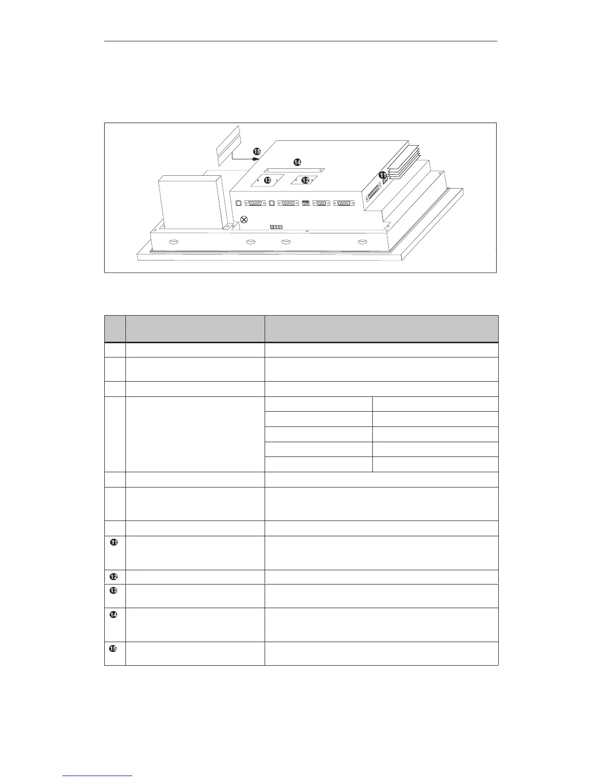
Figure 17-2 OP37: Arrangement of connections
No
.
Name Description
Ê
Chassis ground –
Ë
Power supply/Relay output Power supply (+ 24 V DC) and contact assemblies for driving a
horn or a light, for example.
Ì
PS2 keyboard connection For DOS mode only
Serial interfaces
Level Usage
Í
IF1A V.24/TTY (active/passive) PLC
Ï
IF2 V.24/TTY (active/passive) PC, PU, printer
Ñ
IF1B RS422/RS485 PLC
Ò
IF3 TTY (passive)/RS422/RS485 Not used at present
Î
PS2 mouse connection For DOS mode only
Ð
DIP switch For setting serial interface IF1B (refer to Appendix B). Set and
check with the table in Section , 13.1.2Configuring the IF1B inter-
face.
Ó
Parallel interface LPT1 For parallel printer
Relay output Contact assembly for temperature monitoring and driving a light or
an auxiliary blower, for example. The relay is tripped when the
outside temperature reaches 45 °C.
Battery compartment (covered) –
Direct key module or CPI (optional) For connecting a direct key module with 12/ 16 digital outputs or a
control panel interface with max. 16/32 digital inputs/outputs.
AT expansion slot connection Connection of an AT expansion slot for accommodating two short
AT cards. (The AT expansion slot is not supported by the OP firm-
ware.)
PCMCIA Slot A and Slot B For JEIDA/PCMCIA cards (Slot A is for DOS mode only, Slot B
for OP and DOS modes)
OP37
Unit Description
Artisan Technology Group - Quality Instrumentation ... Guaranteed | (888) 88-SOURCE | www.artisantg.com
 Loading...