Detailed descriptions
16.1 Motherboard
SIMATIC IPC647C
160 Operating Instructions, 12/2010, A5E02669337-02
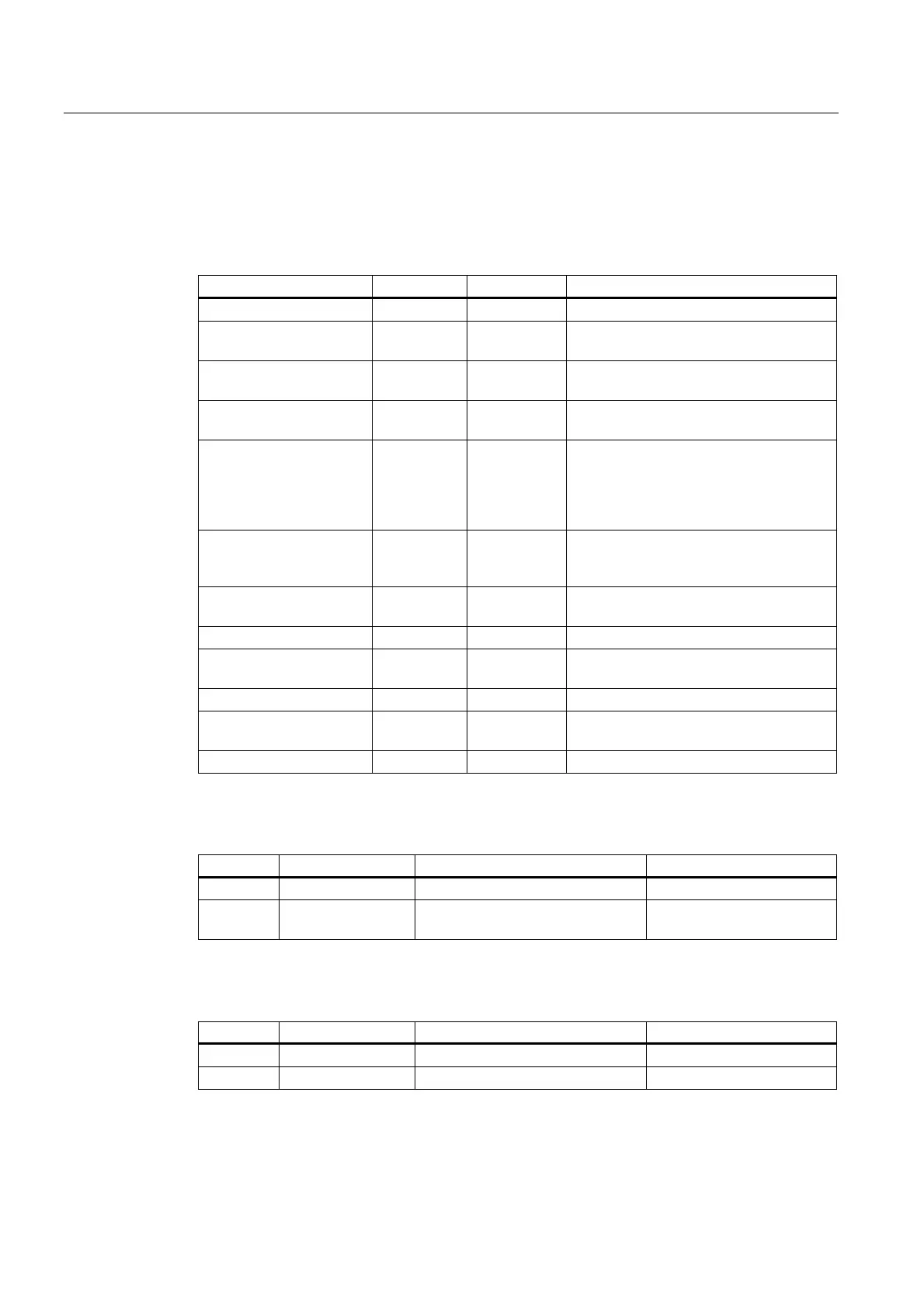
16.1.5 Internal ports
Pin assignment of the internal interfaces
Interface Position Connector Description
Memory Internal X19, X20 2 DIMM sockets, 64-/ 72-bit
Bus expansion Internal X10 Bus expansion socket, used by PCI and
PCIe bus signals
Power supply Internal X9 4-pin 12 V ATX power connector
(CPU-VRM supply)
Fan monitoring Internal X130 Power supply fan monitoring
8-pin pin header
Floppy Internal X608 Two drives can be installed (82078
compatible) 360 KB, 720 KB, 1.2 MB,
1.44 MB 3F0h–3F7h, 370h–377h, IRQ 6
can be disabled, edge triggered 34-pin,
socket for standard floppy disk drive
SATA Internal (hard
disk drive, for
example)
X50, 51, 52,
53, 54, 55
SATA connector, 7-pin
Connection for device fan Internal X132, X131 Power supply, device fan monitoring
(controlled), 4-pin, pin header
Connection for SCSI LED Internal X12 Input for SCSI drive activity display
Internal USB interface Internal X420 For connecting the USB cable to the front
panel of the computer
Front panel interface Internal X46 OP connection
RAID HDD Alarm Internal X11 2-pin plug, LED interface for hard disk or
removable racks 1 and 2
Port 80 connector Internal X45 Connection for Port 80 / mode switch
Assignment of the SCSI activity connector, X12 Type JST B2B-PH-SM3-TB
Pin no. Short name Meaning Input / output
1 NC - -
2 SCSI HD_N 0-V level means that the SCSI
interface is active
Input
External Reset, X6, Type JST B2B-PH-SM3-TB
Pin no. Short name Meaning Input / Output
1 GND Ground -
2 Reset 0 V level means reset Input

 Loading...