Introduction to CPU 410-5H
2.4 The basic system for redundant operation
CPU 410-5H Process Automation
System Manual, 09/2014, A5E31622160-AB
27
The basic system for redundant operation
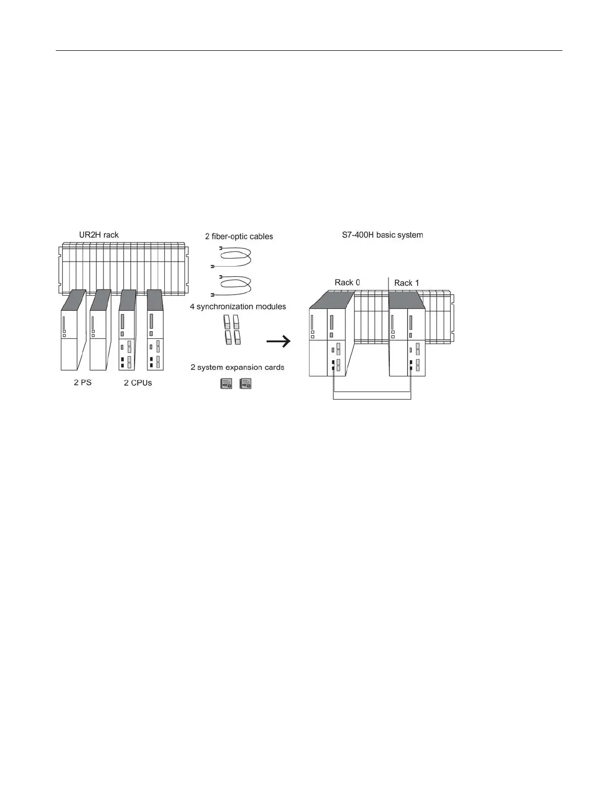
Hardware of the basic system
The basic system consists of the hardware components required for a fault-tolerant
controller. The following figure shows the components in the configuration.
The basic system can be expanded with standard modules of the S7-400. There are
restrictions for the function modules and communication processors. See Appendix Function
and communication modules that can be used in a redundant configuration (Page 335).
Figure 2-3 Hardware of the S7-400H basic system
The two CPUs are the heart of the S7-400H. Use the switch
of the CPU to set
the rack numbers. In the following sections, we will refer to the CPU in rack 0 as CPU 0, and
to the CPU in rack 1 as CPU 1.
The UR2-H rack supports the installation of two separate subsystems with nine slots each,
and is suitable for installation in 19" cabinets.
You can also set up the S7-400H in two separate racks. The racks UR1, UR2, and CR3 are
available for this purpose.
 Loading...