EasyManuals Logo
Home>Siemens>Controller>SIMATIC PCS 7 CPU 410-5H

Siemens SIMATIC PCS 7 CPU 410-5H User Manual

Siemens SIMATIC PCS 7 CPU 410-5H
380 pages
To Next Page IconTo Next Page
To Previous Page IconTo Previous Page
Page #342 background imageLoading...
Page #342 background image
Connection examples for redundant I/Os
C.6 SM 321; DI 32 x DC 24 V, 6ES7 321–1BL00–0AA0
CPU 410-5H Process Automation
342 System Manual, 09/2014, A5E31622160-AB
C.6
SM 321; DI 32 x DC 24 V, 6ES7 321–1BL00–0AA0
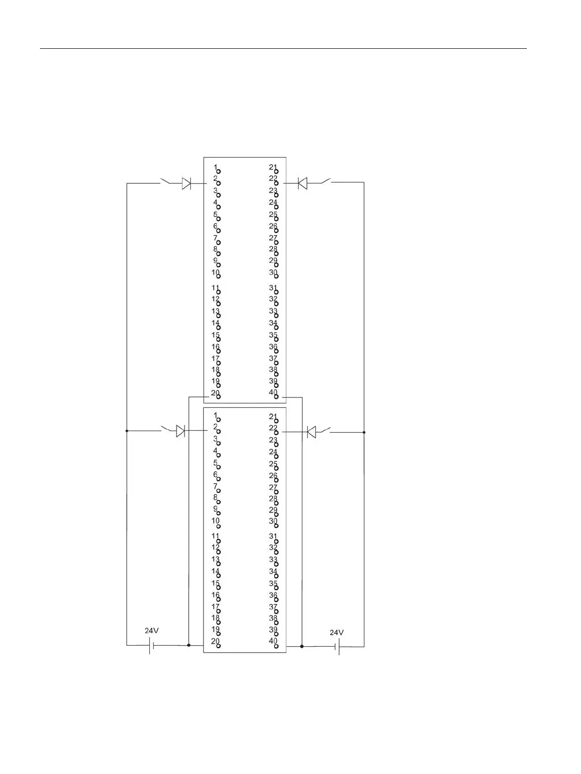
The diagram below shows the connection of two redundant encoder pairs to two redundant
SM 321; DI 32 x DC 24 V. The encoders are connected to channel 0 and channel 16
respectively.
Figure C-4 Example of an interconnection with SM 321; DI 32 x DC 24 V

Table of Contents

Questions and Answers:

Question and Answer IconNeed help?

Do you have a question about the Siemens SIMATIC PCS 7 CPU 410-5H and is the answer not in the manual?

Siemens SIMATIC PCS 7 CPU 410-5H Specifications

General IconGeneral
BrandSiemens
ModelSIMATIC PCS 7 CPU 410-5H
CategoryController
LanguageEnglish

Related product manuals