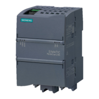
Structure of the CPU 410-5H
3.1 Operator controls and display elements on the CPU 410-5H
CPU 410-5H Process Automation
36 System Manual, 09/2014, A5E31622160-AB
The following table shows an overview of the LED displays on the individual CPUs.
Sections Monitoring functions of the CPU 410-5H (Page 39) and Status and error displays
(Page 41) describe the states and errors/faults indicated by these LEDs.
Table 3- 1 LED displays on the CPUs
REDF red Loss of redundancy/Redundancy fault
Bus fault at the PROFIBUS interface
BUS5F red Bus fault at the first PROFINET IO interface
Bus fault at the second PROFINET IO interface
Error in synchronization module 1
Error in synchronization module 2
Maintenance request pending
Connection at the PROFINET IO interface is active
Receiving or sending data at the PROFINET IO interface.
Connection via synchronization module 1 is active and OK
Connection via synchronization module 2 is active and OK
You operate the reset button in the following cases:
● You want to reset the CPU to the factory state, see section Resetting the CPU410-5H to
factory settings (Page 141)
● You want to reset the CPU during operation, see section Reset during operation
(Page 143)
The reset button is on the front of the CPU directly below the LED strip. Use an appropriately
narrow object to press the reset button.

 Loading...


