12 – 5
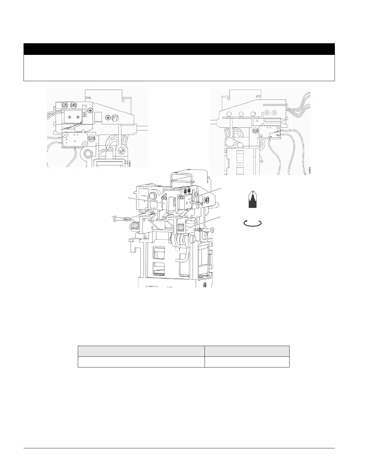
12.3.1 Trip Signaling Switches S13, S24, and S26
(1) S26 assembled with snap-in pins
(2) S13 snap in assembly
(3) S25 / S45 assembled with self-tapping screws
(4) S24 assembled with snap-in pins
The connecting wires from the signaling switches must be connected to secondary disconnects X8 and X9 according to the
wiring plan (page 8-3) and (page 8-6).
NOTICE
Over-tightening the mounting screws may deform the signaling switch and could lead to an incorrect indication
of breaker status.
Hardware shall be tightened carefully until the underside of the screw head is flush with the mounting surface.
Signaling switches Catalog No.
Bell Alarm S24 (1 form C contact) WLBA
(2)
(1)
(3)
(4)
PZ 1
hand tighten

 Loading...