8 – 1
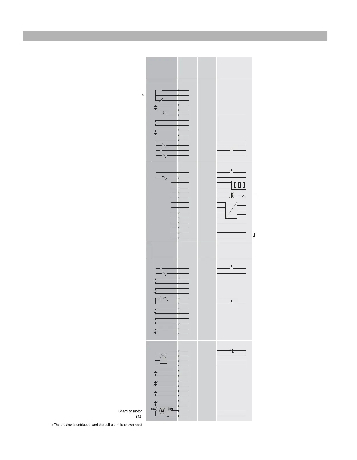
8 Circuit diagrams
8.1 Terminal assignment
1
2
3
4
5
6
7
8
9
10
11
12
13
14
Remote reset Bell Alarm & tripped indicator F7
CUB +
CUB -
24 V DC
0 V DC
External Iron Core Ground Fault Sensor S2
External Air Core Neutr
al
Sensor S1
External Air Core Neutr
al
Sensor S2
External voltage transformer L1
External voltage transformer L2
voltageExternal transformer L3
External voltage transformer Com
COM15/16, otherwise empty
1
2
3
4
5
6
7
8
9
10
11
12
13
14
S 2
S 2
“Ready to close” signal S20
Closing Coil CC
S1
S1
1st Shunt Trip.
X8
X7
X6
X5
1
2
3
4
5
6
7
8
9
10
11
12
13
14
S 4
S 4
S 3
S 3
2nd :auxiliary release F3 "UVR", F4 "UVR td"
F4 only “quick OPEN”
0053-07_n
u
Internal
External
Terminals
ANSI
C37.2
device
#
LT / (+)
Control power
N / (-)
EMERGENCY OPEN
or short terminals
Phase A
Phase B
Phase C
24 V DC Input
Terminating resistor if no
external CubicleBUS module is connected
, 120 , 0.5 WΩ
Short terminals, if no Neutral sensor
1
2
3
4
5
6
7
8
9
10
11
12
13
14
30
52CS
52CC
52CS
52TC
79
52TC / 86
52a
52b
52b
52b
52a
52a
52LC
52CC
52a
52b
52M
62
27
Signalling switch for 2nd shunt trip
Signaling switch for remote tripping
Bell Alarm S24
Open Fuse Indication S26
2nd shunt trip F2
X9
LT / (+)
Control power
N / (-)
LT / (+)
Control power
N / (-)
LT / (+)
Control power
N / (-)
LT / (+)
LT / (+)
Control power
Control power
Fuse carriage FS III
N / (-)
X9.3
X9.4
LT / (+)
Control power
N / (-)
OFLO
BA
TC
TC
CC
b
a
a
a
b
a
b
b
External Iron Core Ground Fault Sensor S1
Open Fuse Lockout Device (FS III Only)
Optional motor disconnect switch

 Loading...