19 – 2
19.1.1 General notes
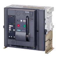
(1) Output 1
(2) Holes with press nut for socket head cap screw M6 with washer for the configuration of the mechanical circuit breaker interlocking
(3) Non-interchangeable brackets
(4) Input 1
(5) Input 2
(6) Output 2
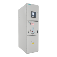
In the following configuration instructions, the following designations apply:
A
1
: Output signal 1
E
1
: Input signal 1
S
1
: Circuit breaker 1
For example, in order to couple the output signal 1 of circuit breaker 1 with the input signal 2 of circuit breaker 2,
the abbreviation S
1
A
1
- S
2
E
2
is used.
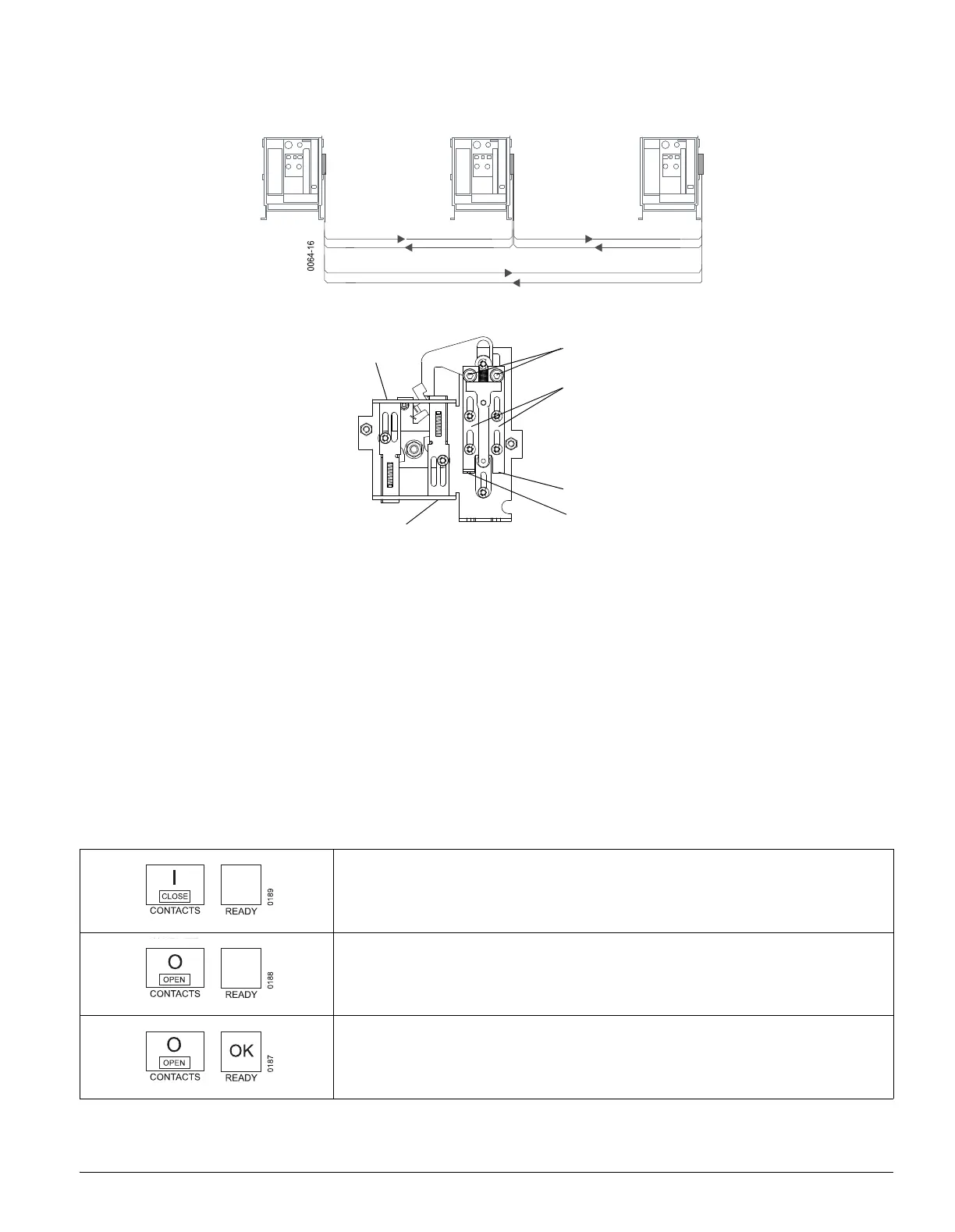
The states of the circuit breaker are shown at the front panel:
Circuit breaker closed
Circuit breaker open and not ready to close
(interlocked)
Circuit breaker open and ready to close
(not interlocked)

 Loading...