5 – 5
5.2 Main terminal connections
For main terminal dimensions of individual frame sizes, refer to: Frame sizes / dimension drawings (page 7-1)
The main terminals and connectors are intended for busbar connection with NEMA hole patterns.
The number and size of the busbars connected to the circuit breaker must be selected per ANSI C.37.20.1 in order to meet the test require-
ments according to ANSI C.37.51 depending on the rated current, defined by the rating plug. Different bussing in a given frame size may be
applicable.
5.2.1 Cradle connections
1) The terminal permits the use of 2“ x ¼“ busbars is possible.
2) The terminal permits the use of 4“ x ¼“ busbars is possible.
5.2.2 Horizontal connections for 4-pole fixed mount breakers
1) The terminal permits the use of 2“ x ¼“ busbars is possible.
5.2.3 Vertical connections for 4-pole fixed mount breakers
1) The terminal permits the use of 2“ x ¼“ busbars is possible.
2) The terminal permits the use of 4“ x ¼“ busbars is possible.
3) The FSII 3200 A and FSIII 4000 A, 5000A require vertical connectors.
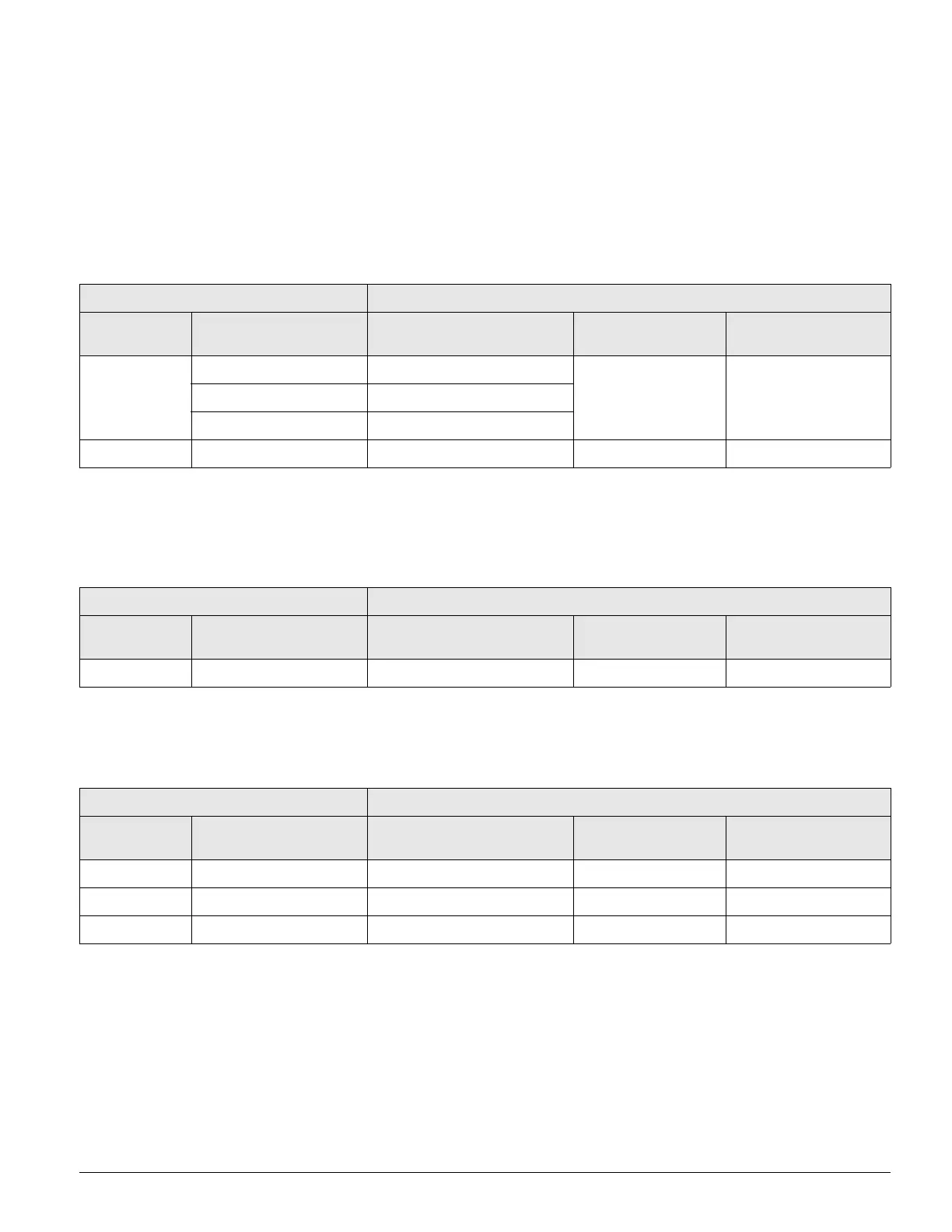
Drawout Circuit breaker Connections to Line/Load side cradle connectors
Frame Size I
n max
Number of Available Busbar
Mounting Positions
Busbar cross-section Number of holes
II
800 A / 1600 A 1 - 3
4“ x ¼“
1)
42000 A 2 - 4
3200 A 3 - 5
III 4000 A / 5000 A 5 - 7 5“ x ¼“
2)
6
Fixed mount Circuit Breaker Connection to Line/Load side horizontal terminals
Frame Size I
n max
Number of Available Busbar
Mounting Positions
Busbar cross-section Number of holes
II 800 A / 1600 A / 2000 A 1 - 4 4“ x ¼“
1)
2
Fixed mount Circuit Breaker Connection to Line/Load side terminals with vertical connectors
Frame Size I
n max
Number of Available Busbar
Mounting Positions
Busbar cross-section Number of holes
II 800 A / 1600 A / 2000 A 1 - 4 4“ x ¼“
1)
2
II 3200 A
3)
1 - 4 4“ x ¼“
1)
2
III 4000 A / 5000 A
3)
5 - 7 5“ x ¼“
2)
6

 Loading...