13 – 4
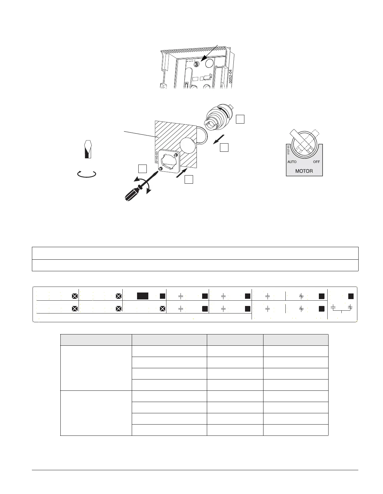
Installing the selector knob
- Factory installed accessory only. Available as replacement kit
Circuit diagrams (page 8-6)
13.3 Updating the options label
NOTE
After installing additional components, mark the following data with a "x", using an indelible ink pen.
Voltage Power consumption Catalog No.
Motor-operated mechanism
24 V DC / 30 V DC 110 W WLELCMTR24
48 V DC / 60 V DC 120 W WLELCMTR48
110-127 V AC / 110-125 V DC 150 W WLELCMTR120
208-240 V AC / 220-250 V DC 130 W WLELCMTR240
Motor-operated mechanism
with motor disconnect switch
24 V DC / 30 V DC 110 W WLELCMTR24S
48 V DC / 60 V DC 120 W WLELCMTR48S
110-127 V AC / 110-125 V DC 150 W WLELCMTR120S
208-240 V AC / 220-250 V DC 130 W WLELCMTR240S
4
3
2
1
Front Panel
3,0 x 0,6
hand tighten
Siemens Industry, Inc., Fort Worth, TX 76155 USA
Charging Motor
Remote Close Coil
X5-2 (+)
X5-1 (-)
X6-7 (+)
X6-8 (-)
240
250
VAC
VDC
120
125
VAC
VDC
240
250
VAC
VDC
120
125
VAC
VDC
VAC
VDC
120
125
VAC
VDC
1st Shunt Trip
UVR
2nd Shunt Trip
Remote Reset
X6-13 (-)
X6-14 (+)
X5-11 (-)
X5-12 (+)
X9-1 (-)
X9-2 (+)
X8-13 (-)
X8-14 (+)
Ready to Close Switch
X6-5
X6-6
240 VAC
4A
240 VAC
1st Shunt Trip Switch
X9-7
X9-8
240 VAC
240 VAC
UVR Switch
Open Fuse Switch
X9-10
X9-11
X9-5
X9-6
52a 1st Aux. SW. 52b
X6-3
X6-4
X6-11
X6-12
X6-1
X6-2
X6-9
X6-10
X5-5
X5-6
X5-9
X5-10
X5-3
X5-4
X5-7
X5-8
52a 2nd Aux. SW. 52b
240 VAC ,
Bell Alarm
240 VAC
5A
5A
X9-13
X9-14X9-12
3A
3A
Assembled in USA
10 A / 125 VDC , 0.5 A / 24 VDC , 3A
0131-FW

 Loading...