To use.
■
Click the Trigger Type box and select Bus from the drop-down list.
■
Click the Bus box and select the bus number or name from the drop-down list. The Bus Type shows Parallel.
■
Click the Logic Thresholds Setup button to set the voltage threshold levels for the channels in the bus.
■
Click the Pattern box and select the condition.
■
Double-click the Time entry box and use the keypad or the multipurpose knob to enter a time.
■
When All is selected in the Bus box, click the Trigger if Logic State Goes True box and select True or False.
■
Click the Edit button to define a numeric or symbolic value of the Pattern.
■
Click the Format box and select a Binary, ASCII, Decimal, Hex, or Symbolic display format.
What do you want to do next?
Learn how to define a pattern for a bus.
Learn how to set the voltage threshold reference level for logic waveforms and to define a pattern.
Learn about bus setups.
Learn about bus configuration.
Learn about digital setups.
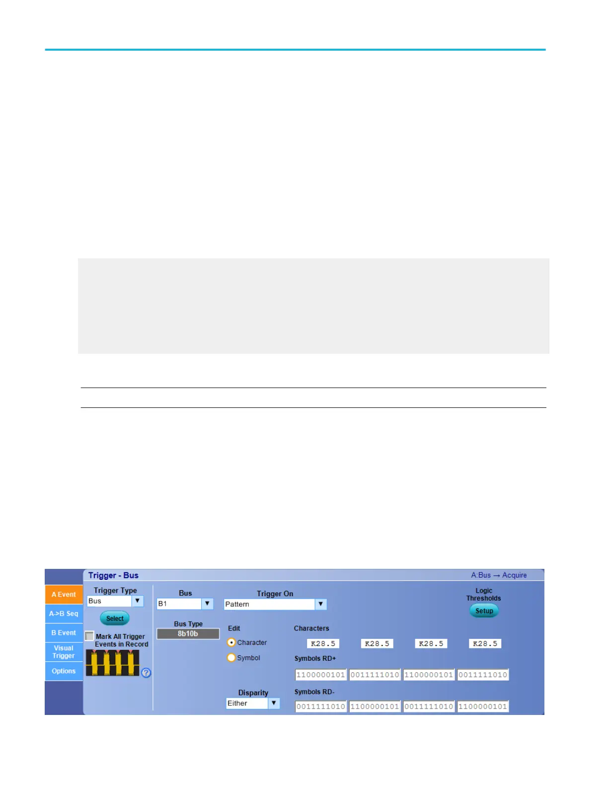
Set up an 8B10B bus trigger
NOTE. The Bus Trigger Control Window for 8B10B Serial option is available only on instruments with option SR-810B.
From the Trigger menu, select Bus setup.
Overview. Use the controls to set up the 8B10B Bus parameters.
To use. For information on the controls, click the buttons.
■
Trigger Type
■
Mark All Trigger Events
■
Bus
■
Logic Thresholds
Trigger setups
384 DPO70000SX, MSO/DPO70000DX, MSO/DPO70000C, DPO7000C, and MSO/DPO5000B Series
 Loading...