Logic pattern format
NOTE. This online help file supports many oscilloscope models from Tektronix. This feature is only available on some models.
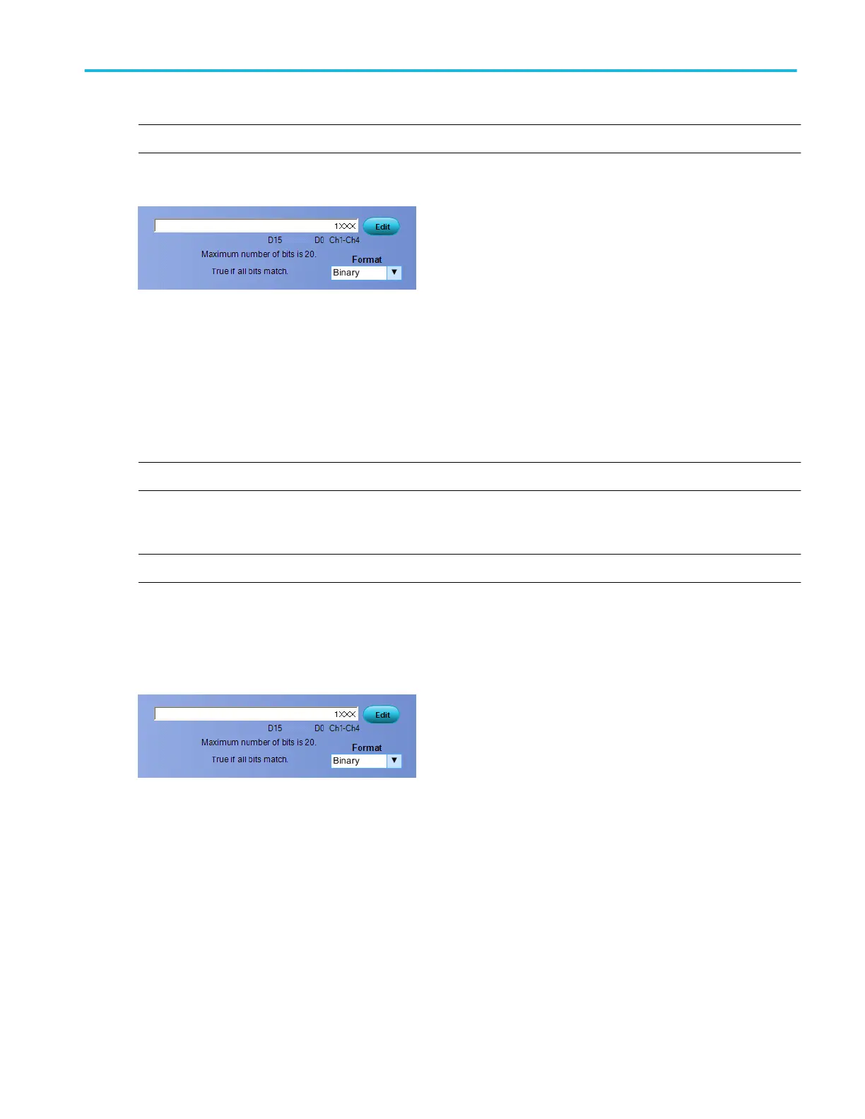
Select the Logic Pattern or Logic State trigger type. You can change the format of the pattern after you define a logic pattern.
■
ASCII causes the instrument to represent the bus pattern value as an ASCII value.
■
Decimal causes the instrument to represent the bus pattern value as a decimal value.
■
Hex causes the instrument to represent the bus pattern value as a hexadecimal value.
■
Binary causes the instrument to represent the bus pattern value as a binary value.
Logic pattern setup
NOTE. This online help file supports many oscilloscope models from Tektronix. This feature is only available on some models.
Use the controls to set up the Logic Pattern or Logic State trigger pattern. Click the Edit button to access the Pattern Editor dialog
box.
NOTE. The Logic Pattern or Logic State trigger setups include the D15-D0 digital channels.
For information on the Pattern Editor dialog box, click the buttons.
■
Bus Pattern
■
Digital Pattern
Logic state inputs
Channels 1, 2, and 3 represent the data inputs. Channel 4 should be connected to the clock signal. The channel inputs combine
to form a logic pattern.
Each channel can have a value of high (H), low (L), or "don't care" (X).
■
A value is considered high if the channel input voltage is greater than the specified threshold voltage.
■
A value is considered low if the channel input voltage is less than the specified threshold voltage.
■
Use the "don't care" selection for any channels that will not be used as part of the pattern.
Oscilloscope reference
DPO70000SX, MSO/DPO70000DX, MSO/DPO70000C, DPO7000C, and MSO/DPO5000B Series 781
 Loading...