What do you want to do next?
Learn about digital setups.
Learn about bus setups.
Learn about bus configuration.
Troubleshooting circuits using a parallel bus
NOTE. This online help file supports many oscilloscope models from Tektronix. This feature is only available on some models.
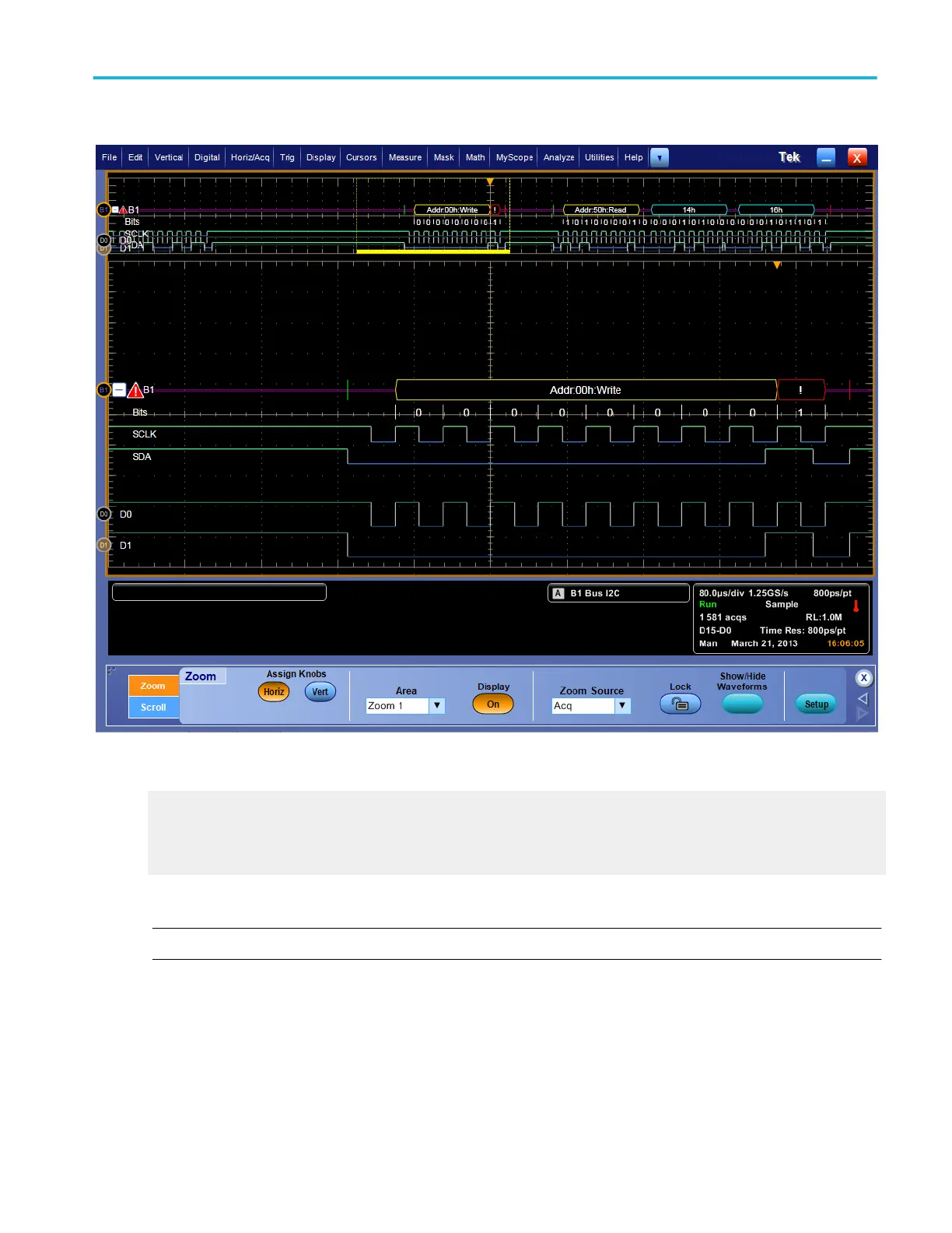
You can use digital, analog, or math waveforms to create, monitor, and analyze a parallel bus with your instrument. The
supported instruments let you see the on-off status of the signals and decodes the parallel bus signals for you.
1. Connect a logic probe to the logic probe port on the front panel.
2. Connect the logic probe tips for data to test points for signals of interest in your system under test. For parallel buses that
include a clock signal, connect the Clock probe tip to a clock signal in your system under test.
3. From the File menu, select Recall Default Setup. Push the Chl 1 button to remove the waveform from the display.
4. From the Digital menu, select Digital Setup.
How to ?
DPO70000SX, MSO/DPO70000DX, MSO/DPO70000C, DPO7000C, and MSO/DPO5000B Series 587
 Loading...