5. Click the digital channel buttons for the channels you plan to use in your parallel bus. For a wider bus, click the other tab
and select more digital channels. To remove a channel, click the channel button again.
6. From the Digital menu, select Bus Setup.
7. Click Parallel as the Bus Type.
8. Click the Add Sources Select button.
9. In the Bus Source Selection dialog, click the channels to use in the parallel bus. Click OK.
10. Arrange the channels in the desired bit order in the Bus Contains list of channels. To change the bit order of a channel in the
bus, select the channel, and click the up or down arrows to move the channel to a more or a less significant bit position.
11. Click the Thresholds Setup button, double-click the Threshold entry box for each channel used, and use the keypad or the
multipurpose knobs to change the voltage reference threshold level. You can also set all the thresholds to the same level
with the Global Thresholds entry box. Click OK.
12. To include a clock signal, click the Clocked check box. Then, click the Clock Source box, select the appropriate channel
from the drop-down list, and also select which edge to use in the Clock Polarity box: Rising, Falling, or Either.
13. Click the Display tab and set the bus display parameters. The instrument acquires, decodes and displays data from the bus
customized for you to readily interpret and analyze activity on the bus.
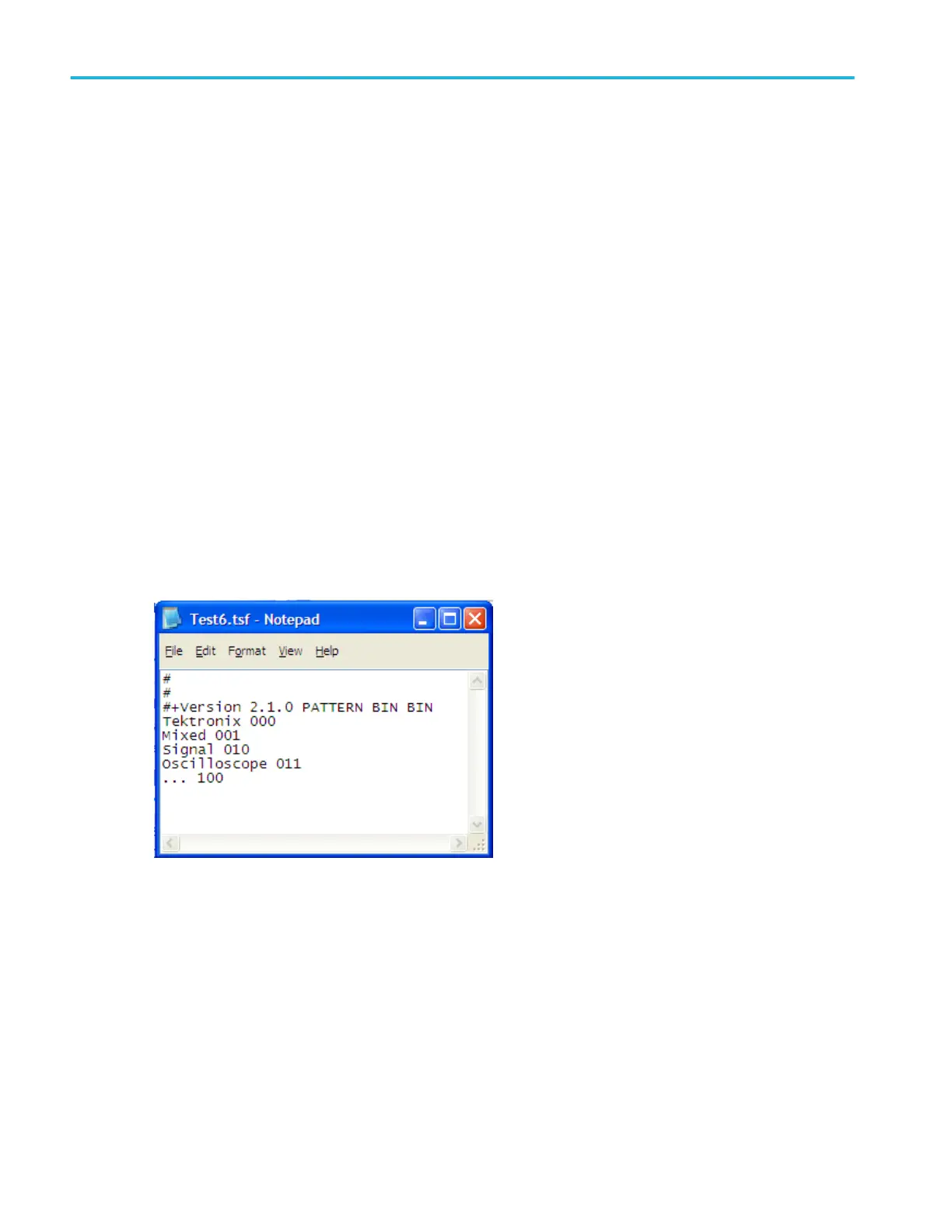
14. To decode the parallel bus with a symbol table file, click the Use Symbol check box, and enter the full path to the file in the
entry box or use the Browse button to locate the file. The file must reside on the instrument in the C:\Users\[Username]
\Tektronix\TekScope\busDecodeTables directory.
Here is the symbol table file used in this troubleshooting example.
15. Acquire data and analyze the physical layer. If an analog channel is displayed, you can use Cursors to take manual
measurements or you can take automatic measurements.
16. Turn the Horizontal Scale knob to adjust the time base.
As you increase the time per division, you will see more data appear in the Bus display.
17. From the Trig menu, select the Bus trigger type.
18. Click the Bus box and select the appropriate bus setup <B1-B16> to acquire data from the parallel bus.
19. Click the Trigger If Logic State Goes box , and select True or False.
20. Click the Edit button, select the Format as Binary, Hex, or Symbolic, and enter a bus pattern for the instrument to use as the
trigger event. Click OK.
How to ?
588 DPO70000SX, MSO/DPO70000DX, MSO/DPO70000C, DPO7000C, and MSO/DPO5000B Series
 Loading...