Home
Tektronix
Test Equipment
MSO73304DX
Tektronix MSO73304DX Printable Help
4
of 1
of 1 rating
920 pages
Give review
Manual
Specs
To Next Page
To Next Page
To Previous Page
To Previous Page
Loading...
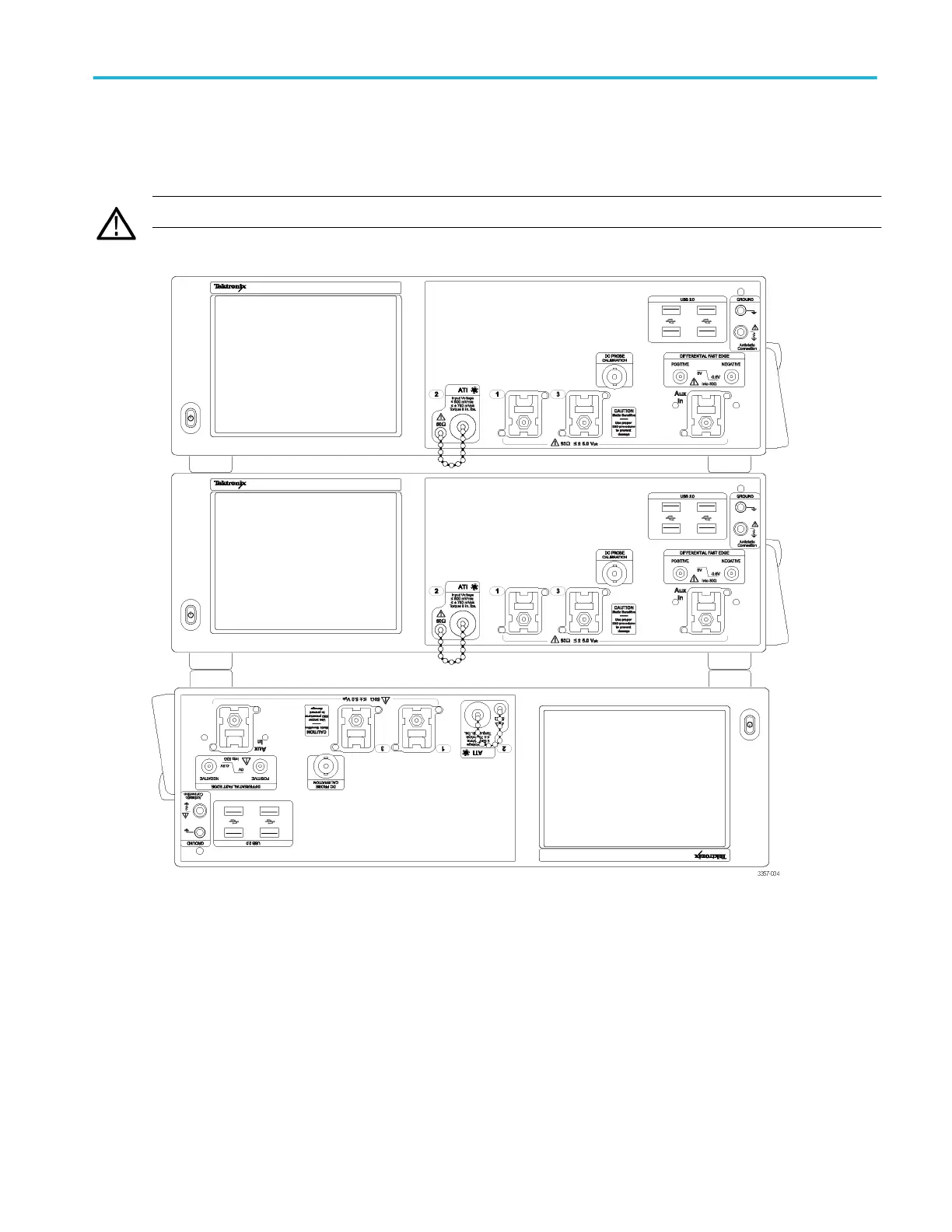
Instrument stacking.
Multiple instruments may be stacked to save space and allow shorter cables and more convenient
connections.
WARNING.
When using an instrument upside down, be careful to avoid pinching your fingers.
About Tektronix oscilloscopes
DPO70000SX, MSO/DPO70000DX, MSO/DPO70000C, DPO7000C, and MSO/DPO5000B Series
47
78
80
Table of Contents
Default Chapter
5
Table of Contents
5
Introduction
31
About Tektronix Oscilloscopes
33
Product Description
33
Signal Processing Features
35
Display Features
35
Measurement Features
35
Trigger Features
35
Convenience Features
35
Product Software
36
Options and Accessories
36
Recommended Accessories
36
Options
42
Documentation and Technical Support
47
Documentation
47
Support Information
48
Tekscope Recovery Report Utility
49
Feedback
50
Analysis and Connectivity Support
51
About Tekscope
53
Working with Your Tektronix Oscilloscope
54
Windows Environment
54
Oscilloscope Interface
59
Basic Operations
65
Multi-Instrument Configuration
78
DPO7AFP Auxiliary Front Panel (Optional)
93
Waveform Operations
94
Controls and Connectors
101
Front Panel Controls and Connectors
101
Front Panel Overview
101
Touch Screen
105
Wave Inspector Controls
106
Vertical Controls
106
Horizontal Controls
107
Trigger Controls
108
Trigger Coupling
110
Run Controls
110
General Purpose Controls
111
Multiview Zoom Controls
112
Rear and Side Panel Connectors
113
Cursor Setups
117
Cursor Setup Control Window (YT Display Format)
117
Track Mode
118
Cursor Type Control Window
119
Cursor Sources (YT Display)
120
Cursor Style
121
Cursor Position Control Window
122
Horizontal Bar Cursors
123
Vertical Bar Cursors
124
Waveform Cursors
124
Screen Cursors
125
Cursor Track Mode
125
Cursor Measurements
126
Cursor Setup Control Window (XY Display Format)
128
Digital Setups
131
Digital Setup Control Window
131
Setting up Digital Signal Inputs
132
Digital Channel Threshold and Position
133
Turn on or off the Digital Channels D15-D8 and D7-D0
135
Set the Display Size of Logic Channels
136
Set the Global Threshold for Digital Channels
136
Set up Digital Channels
137
Bus Setups
139
Bus Setup Control Window (Config Tab)
139
Bus Selection List
141
Bus Search Selection List
142
Display or Clear a Bus
143
Label a Bus
143
Change the Bus Position
145
Set up an I2C Serial Bus
145
Set up an SPI Serial Bus
147
Set up an RS-232 Serial Bus
148
Set up a USB Serial Bus
150
Set up a MIPI DSI-1 Serial Bus
152
Set up a MIPI CSI-2 Serial Bus
153
Set up an 8B10B Serial Bus
155
Set up a Custom Serial Bus
156
Set up a Pcie Serial Bus
158
Set up a CAN Serial Bus
159
Set up a LIN Serial Bus
161
Set up a FLEXRAY Serial Bus
162
Set up a MIL-1553 Serial Bus
164
Set up an Ethernet Serial Bus
165
Select the Number of Lanes
167
Select the Serial Bus Channel Type
167
Select the Serial Bus Channel Input
168
Select the USB Serial Bus Speed
169
Select the USB Bus Signal Type
170
Select the Data Rate
170
Select the Serial Bus Input
171
Select the USB Bus Threshold
171
Select the Serial Bus Channel Threshold
172
Select the SPI Bus Channel Polarity
173
Select the RS-232 Bus Channel Polarity
173
Select the RS-232 Bus Data Bits
174
Select the RS-232 Bus Parity
175
Select the RS-232 Bus Bit Rate
175
Select the SPI Bus Framing
176
Set the SPI Bus Idle Time
177
Set the SPI Bus Word Size
177
Select the SPI Bus Bit Order
178
Set up a Parallel Bus
179
Set up a Clocked Parallel Bus
180
Add Sources to a Parallel Bus
181
Set up Bus Channel Thresholds
182
Change the Bit Order of a Channel in a Parallel Bus
183
Remove a Channel from a Parallel Bus
184
Select the Bus Clock Source Channel
184
Select the Bus Clock Channel Polarity
185
Bus Setup Control Window (Display Tab)
186
Select the Bus Display View
189
Select the Bus Decode Method
190
View Bus Packet
190
Select the Bus Symbol Table
191
Symbol File Format
192
Opening a Bus Symbol Table File
193
Magnivu Setup
195
Using Magnivu
195
Display Setups
199
Display Control Window (Appearance Tab)
199
Display Control Window (Screen Text Tab)
200
Text Properties Control Window
201
Display Control Window (Objects Tab)
202
Display Control Window (Colors Tab)
203
Display Persistence
204
Select the Display Format
205
XY Format Pairs
206
Set the Waveform Intensity
206
Select the Waveform Interpolation
207
Select the Graticule Style
208
Define the Color Palette
209
Remote Operation
211
Horizontal and Acquisition Setups
213
Horizontal-Acquisition Control Window (Horizontal Tab)
213
Set Record Length Limit
214
Horizontal Digital Control Window
215
Horizontal Position-Scale Control Window
216
Horizontal Position-Scale Control Window with Delay Mode on
217
Horizontal-Acquisition Control Window (Acquisition Tab)
218
Autoset
219
Set Autoset Preferences
221
Undo an Autoset
221
Enable Enhanced Effective Number of Bits
222
Enable Fast Acquisitions
223
Start and Stop Waveform Acquisitions
224
Enable Roll Mode
225
Select a Sampling Mode
226
Set the Resolution
228
Select the Acquisition Mode
229
Acquisition Interval
230
Fastframe Control Windows
230
Set up Zoom
232
Error Detector Setups
235
Use the Serial Error Detector
235
Set up the Serial Error Detector
236
Set Error Detector Advanced Settings
238
Specify the Error Detector Test Pattern
239
Set the Error Detector Stop Condition
240
Error Detector Overview
240
Linktraining
243
Link Training Environment
243
Link Training Connections
244
Start Link Training
245
Typical Link Training Display
246
Results Table
247
Using Link Training from the Programming Interface
247
Mask Testing Setups
249
Mask Setup
249
Mask Testing Control Window (Masks Tab)
249
Serial Mask Testing Option
250
Select a Mask Type
250
Mask Types and Standards
251
Use Mask Display Controls
252
Mask Configuration Controls
253
Set up Mask Alignment
256
Edit a Mask
257
Tolerance Setup
258
Set up Mask Testing Source-Tolerance
258
Set up Mask Margins
258
Fail Setup
259
Set up Pass-Fail Mask Testing
259
Set up Mask Test Fail Notification
260
Set up Mask Test Completion Notification
261
Set Mask Test Parameters
262
Select the Sound Source
263
Set the Mask Polarity
264
Set Mask Test Repeat Controls
264
Fail Results Setup
265
Mask Testing Control Window (Pass-Fail Results Tab)
265
View the Mask Test Summary
266
View the Mask Hits Per Segment
267
Start or Reset a Mask Test
268
User Mask Setup
268
Set the User Mask Controls
268
Set User Mask Edit Controls
270
Recall User Mask
270
Limit Test
272
Set up Limit Testing
272
Save a Template
273
Set up Limit Test Failure Notification
274
Math Setups
277
Set up a Math Waveform
277
Set up Math Averaging
278
Set Math Variables
279
Custom Analysis Functions
279
Use Custom Analysis Functions
280
MATLAB Custom Analysis Interface
280
Basic Spectral Setups
281
Set up Basic Spectral Analysis
281
Use Front Panel Spectral Controls
282
Advanced Spectral Setups
282
Set up Advanced Spectral Analysis
282
Set up the Frequency Spectral Controls
283
Set up Spectral Gating Controls
285
Using Spectral Analysis
287
Spectral Analysis Overview
287
Spectral Analysis Features
287
FFT Process
287
The FFT Display
288
FFT Windows
289
FFT Window Characteristics
290
Time Domain Gating
290
Aliasing
291
Eliminate Aliasing
291
Math Equation Editor
292
Math Equation Editor Control Window
292
Math Equation Editor (Time Tab)
293
Math Equation Editor (Spectral Tab)
297
Math Equation Editor (Var Tab)
298
Math Equation Editor (Meas Tab)
298
Math Equation Editor (Filter Tab)
299
Measurement Setups
301
Measurement Snapshot Control Window
301
Measurement Setup Control Window (Amplitude Tab)
302
Measurement Readouts
303
Select an Amplitude Measurement
304
Measurement Setup Control Window (Time Tab)
307
Select a Time Measurement
308
Measurement Setup Control Window (Communications Tab)
310
Select a Communications Measurement
312
Measurement Setup Control Window (more Tab)
314
Select a Miscellaneous Measurement
316
Counter Measurement Setup
317
Set up Measurement Statistics
319
Set up Reference Levels
320
Set up Measurement Gating
322
Set up Histogram Measurements
323
Set up Histograms
324
Analyzing Waveforms
329
Control Marks
329
Select a Search Type
330
Select the Search Type
331
Select the Search Source
331
Configure a Search
333
Copy Search Settings
334
Set Advanced DDR Search Settings
335
Set Search Parameters
336
Check Search Results
337
View the Search Counts Results
338
View Search Marks
339
Set the Search Mode
339
Use Search and Mark Controls
340
Control User Marks in Table
342
Change Mark Display Digits
342
Export a Mark Table
343
View Mark Counts
344
Set up a Visual Search
344
Set up 8B10B Search Parameters
346
Set up RS-232 Search Parameters
348
Set up SPI Search Parameters
351
Set up I2C Search Parameters
353
Set up USB Search Parameters
357
Set up MIPI Search Parameters
364
Set up Pcie Search Parameters
370
Set up CAN Search Parameters
372
Set up LIN Search Parameters
375
Set up FLEXRAY Search Parameters
378
Set up MIL-1553 Search Parameters
382
Set up Ethernet Search Parameters
385
Set up DDR Search Parameters
391
Set up Custom Search Parameters
393
Set up Parallel Search Parameters
394
View the Results Table
395
Copy the Results Table
399
Select Columns to Copy or Export
400
Save the Results Table
401
Myscope Setups
403
Set up a Myscope Control Window
403
Use a Myscope Control Window
404
Measure Controls
405
Save a Myscope File as a Dialog Box
406
Open or Edit a Myscope Dialog Box
407
Trigger Setups
409
Set up Trigger Controls (a Event Tab)
409
Select the Trigger Type
410
Set the Trigger Mode Controls
412
Set up the Trigger Holdoff
414
Set to 50
415
A Event Triggers
415
Set up a Parallel Bus Trigger
415
Set up an 8B10B Bus Trigger
416
Set up an I2C Bus Trigger
418
Set up an SPI Bus Trigger
420
Set up an RS-232 Bus Trigger
421
Set up a USB Bus Trigger
423
Set up a Pcie Bus Trigger
428
Set up a CAN Bus Trigger
430
Set up a CAN Bus Trigger
431
Set up a LIN Bus Trigger
432
Set up a FLEXRAY Bus Trigger
434
Set up a MIL-1553 Bus Trigger
437
Set up an Ethernet Bus Trigger
439
Set up a Comm Trigger
444
Set up an Edge Trigger
446
Set up a Freq/Period Trigger
447
Set up a Glitch Trigger
449
Set up a Logic Pattern Trigger
452
Set up a Logic Pattern Trigger
453
Set up a Runt Trigger
453
Set up a Serial Pattern Trigger
455
Set up a Setup and Hold Trigger
456
Set up an SPI Bus Trigger
459
Set up a Logic State Trigger
460
Set up a Logic State Trigger
461
Set up a Timeout Trigger
462
Set up a Transition Time Trigger
465
Set up a Video Trigger
467
Set up a Width Trigger
469
Set up a Window Trigger
472
Sequence Triggering
473
Set up Sequential Triggering (Horizontal Delay Off)
473
A Only Trigger
476
Trigger after Time
480
Trigger after Events
484
B Event Trigger
491
Set up Trigger Controls (B Event Tab)
491
Visual Triggering
492
Visual Trigger
492
Create a Visual Trigger Area
494
Control Visual Triggering
497
Define an Area
499
Edit Expression Logic
501
Set up Visual Trigger Expression
502
Select a Channel
503
Enable the Visual Trigger Expression Editor
503
Edit the Visual Trigger Expression
503
Use the Expression Editor Operands
504
Text Edit Controls
504
Save a Visual Setup
505
Recall a Visual Setup
505
Mode and Holdoff
506
Set up Trigger Controls (Options Tab)
506
Enable Trigger Position Correction
508
Vertical Setups
511
Set up Vertical Controls
511
Set up Input Channels
513
Zoom Control Window
515
Waveform Display Control Window
516
Set the Position-Offset
517
Waveform Label Control Window
518
Vertical Offset Control Window
519
Using Offset to Avoid Clipping Signals
520
Termination Controls
520
Coupling Controls
522
Deskew-Attenuation Control Window
523
Bandwidth Control Window
525
Enhanced Bandwidth
526
Vertical Setup Control Window (Aux Tab)
528
Probe Setup Control Window
529
Probe Setup Control Window (Setup Type)
531
Probe Setup Control Window (D15-D0 Tab)
533
Probe Setup Control Window (Probe Compensation)
534
Probe Setup Control Window (Probe Tip Selection)
536
Probe Setup Control Window (Probe Deskew)
537
Probe Setup Control Window (Probe Attenuation)
539
Probe Controls Window
541
Probe Properties
542
Probe Setup Control Window (Probe Status)
543
Signal Path Compensation
545
Signal Path Compensation Status
547
Copying and Printing
549
Copy Setup
549
Copy Setup (Images)
549
Copy Setup (Waveforms)
550
Copy Setup (Measurements)
552
Copying Procedures
553
Copy Waveform Data
553
Copying the Screen for Use in Other Applications
554
Copying Measurements for Use in Other Applications
554
Printing
555
Page Setup Dialog Box
555
Print Preview Dialog Box
555
Print Dialog Box
556
Printing the Screen to a Printer
556
File Menu
559
Reference Waveform Setups
559
Reference Waveform Controls
559
Save as Dialog Box (Waveform)
560
Recall Dialog Box (Waveform)
561
Delete Setups and Reference Waveforms
562
Instrument Setups
563
Save as Dialog Box (Instrument Setup)
563
Recall Dialog Box (Instrument Setups)
564
Delete Setups and Reference Waveforms
565
Action on Event
566
Set up Action on Event
566
Set up Save on Event
567
Print Setups
568
Saving
568
Save as Dialog Box (Histogram)
568
Save as Dialog Box (Instrument Setup)
569
Save as Dialog Box (Measurement)
570
Save as Dialog Box (Screen Capture)
571
Save as Dialog Box (User Mask)
574
Save as Dialog Box (Waveform)
575
Auto-Increment the File Name
576
Save as Dialog Box (Digitals)
576
Save as Dialog Box (Timestamp)
577
Utilities
579
Tek Secure Erase
579
Set Time and Date
580
GPIB Configuration Control Window
581
LAN Server Status Control Window
582
External Signals Control Window
582
Touch Screen
584
Instrument Calibration Control Window
584
Instrument Diagnostics Control Window
586
E-Mail on Event Control Window
587
Measurement Save Options
588
Multipurpose Knobs
590
User Preferences Control Window
591
User Preferences (Prompt before Action)
591
User Preferences (Keypad Defaults)
591
User Preferences (Readouts)
592
User Preferences (Measurement Annotation)
593
User Preferences (Units)
594
User Preferences (Front Panel Buttons)
594
Option Installation
595
Install an Option
595
Install the Floating License
598
Install the Fixed License
600
Return the Floating License for the Installed Option(S)
602
Calibrating and Using Probes
607
Compensate the Signal Path
607
Compensate Active Probes
607
Compensate Passive Probes
608
Low Frequency Compensate a Probe
608
Deskew
608
Acquiring Analog Signals
609
Setting up Analog Channels
609
Setting Acquisition Modes
610
Use Fast Acquisitions
610
View the Analog Characteristics of a Digital Signal
611
Acquiring Digital Signals
612
Set up Digital Channels
612
Displaying Waveforms as a Bus
613
Set up a Bus
613
Set up a Parallel Bus
613
Set up an SPI Serial Bus
614
Set up an I2C Serial Bus
614
Set up an RS-232 Serial Bus
614
Set up a USB Serial Bus
614
Set up a MIPI DSI-1 Serial Bus
615
Set up a MIPI CSI-2 Serial Bus
615
Set up an 8B10B Serial Bus
615
Set up a Custom Serial Bus
616
Set up a Pcie Serial Bus
616
Set up a CAN Serial Bus
616
Set up a LIN Serial Bus
616
Set up a FLEXRAY Serial Bus
617
Set up a MIL-1553 Serial Bus
617
Set up an Ethernet Serial Bus
617
Configuring the Bus Display
617
Analyzing Buses
618
Tracking down I2C Serial Bus Anomalies
618
Troubleshooting Circuits Using a Parallel Bus
619
Troubleshooting an SPI Serial Bus
622
Creating and Using Myscope Control Windows
624
Creating Myscope Control Windows
624
Editing Myscope Control Windows
624
How to ?
607
Taking Measurements
625
Select Cursor Sources
625
Taking Cursor Measurements
627
Taking Automatic Measurements
627
Take Automatic Measurements
628
Localize a Measurement
629
Save Measurements
629
Creating and Using Math Waveforms
630
Using Math Waveforms
630
Create a Math Waveform Using Predefined Expressions
633
Create a Math Waveform with the Equation Editor
634
Create a Math Waveform
634
Using Mask and Limit Testing
635
Set up Mask Testing
635
Create a New User Mask
637
Create a User Mask from a Defined Mask
638
Edit a User Defined Mask
639
Save a User Mask to Disk
640
Recall a User Mask from Disk
640
Create a User Mask with Mask Testing
640
Use Mask Testing
640
Using E-Mail on Event
641
Send an E-Mail on Events
641
Creating Spectral Waveforms
642
Create a Spectral Waveform
642
Define a Spectral Math Waveform
643
Use a Predefined Spectral Math Waveform
646
Using Reference Waveforms
647
Create a Reference Waveform
647
Save Reference Waveforms Using Auto-Increment File Name
647
Recall a Reference Waveform
648
Using Waveforms
648
Save a Waveform
648
Copy Waveform Data
649
Save a Screen Capture
650
Using Horizontal Delay
651
Set the Horizontal Delay
651
Compare Data Using Horizontal Delay
651
Using Roll Mode
651
Set up Roll Mode
651
Using Roll Mode
652
Triggering
652
Checking Trigger Status
652
Set up Triggering from the Front Panel
653
Set up Triggering from the Trigger Setup Window
654
Trigger on a Sequence
655
Trigger on a Event Only
656
Trigger on an Event after a Specified Delay
656
Trigger on a B Event
656
Trigger on a Glitch
657
Trigger on a Runt Pulse
657
Trigger on a Pulse Width
658
Trigger on a Pulse Timeout
659
Trigger on a Pattern
660
Pattern Triggers
661
Trigger on a Logic State
662
Trigger on the Transition Time
663
Trigger on Setup-Hold Time Violations
664
Trigger on Window Threshold Violations
666
Trigger on a Video Signal
667
Trigger on a Communication Signal
667
Trigger on a Bus
668
Mark All Trigger Events
668
Using Histograms
671
Set up a Histogram
671
Take Automated Measurements on Histogram Data
671
Start or Reset Histogram Counting
671
Using Display Modes
672
Display a Waveform
672
Set up XY Display Format
673
Use Multiview Zoom with Waveforms
673
Choosing a Color Palette
674
Choose a Color Palette
674
Customize the Display Palette
674
Saving and Restoring Instrument Setups
675
Save the Instrument Setups
675
Recall an Instrument Setup
676
Delete Instrument Setups
676
Using the Programmer Online Guide
677
Programmer Online Help
677
Using Application Software
677
Oscilloscope Applications Software
677
Add a Software Application to the Instrument
677
Setting up a Dual Display
677
Set up a Dual Display
677
Connecting to a Network
679
Enable a Network Connection
679
Exiting or Minimizing the Oscilloscope Application
679
Exit the Instrument Application
679
Minimize the Instrument Application
679
Shut down the Instrument
679
Adjusting Display Contrast
680
Adjust the Display Contrast
680
Oscilloscope Reference
681
Functional Model
681
Process Overview
682
Waveform Acquisition
683
Signal Connection
683
Probes and Signal Connection
683
Input Conditioning
684
Bandwidth Enhancement
684
Coupling
685
Scaling and Positioning
685
Vertical Acquisition Window Considerations
686
Horizontal Acquisition Window Considerations
688
Horizontal Acquisition Window Interrelated Parameters
689
Independent Versus Shared Window
690
Incompatible Acquisition Features
690
Autoset Considerations
691
Acquisition Hardware
691
Sampling Process
692
Sampling Modes
693
Waveform Record
693
Interleaving
694
Interpolation
694
Trigger Function
695
Triggering Concepts
695
Trigger Sources
696
Trigger Types
697
Trigger Modes
698
Trigger Holdoff
698
Trigger Coupling
699
Trigger Slope and Level
699
Horizontal Trigger Position
700
Delayed Trigger System
700
Advanced Triggering
700
Bus Trigger
701
Communication Trigger
701
Communication Triggering
701
Glitch Trigger
702
Pattern Trigger
702
Runt Trigger
703
Setup and Hold Trigger
703
State Trigger
704
Timeout Trigger
705
Transition Time Trigger
705
Video Trigger
705
Width Trigger
706
Window Trigger
706
Sequential Triggering
706
Triggering with Horizontal Delay off
706
Triggering with Horizontal Delay on
707
Triggering and Horizontal Delay Summary
708
Waveform Display
709
Display Overview
709
Display Elements
710
Customizable Display Elements
712
Acquisition Preview
715
Waveform Display
715
Operations on the Time Base
716
Horizontal Position and the Horizontal Reference Point
716
Using the Multizoom Feature
717
Waveform Measurement
717
Automatic Measurements
717
Measurement Variables
719
Measurement Algorithms
722
Measurements on Envelope Waveforms
730
Missing or Out-Of-Range Samples
731
Measurement Warnings
731
Measurement Errors
732
Cursor Types
732
Histograms
733
Typical Math Waveforms
734
Math Waveforms
735
Math Waveform Differentiation
736
Math Waveform Sources
737
Math Waveform Expression Syntax
738
Offset Position Scale and Math Waveforms
739
Waveform Integration
739
Math Plugins
740
Using Math Plugins
740
Writing Math Plugins
740
MATLAB Custom Functions
746
Spectral Math Waveforms
748
Spectral Math Controls
748
Spectral Math Time Controls
749
Spectral Math Gating Controls
751
Spectral Math Frequency Domain Controls
752
Spectral Math Magnitude Controls
754
Spectral Math Phase Controls
756
Spectral Analyzer Window Types
760
Flattop2 Window
763
Gaussian Window
764
Hamming Window
765
Hanning Kaiser-Bessel and Blackman-Harris Windows
765
Rectangular Window
767
Tek-Exponential Window
768
Recognizing Aliasing
769
Mask Testing
770
Mask Key Points
770
Serial Mask Testing with Mask Testing
771
Levels Used in Taking Eye Measurements
772
Output
773
Saving and Recalling Setups
773
Saving and Recalling Waveforms
774
Saving and Copying Waveform Data
774
Miscellaneous
775
Acos
775
Acquisition Interval
775
Acquisition Window
775
Active Probes
776
Amplitude
776
Analog Oscilloscope Sweeps
776
Area
776
Asin
776
Atan
776
Auto Trigger Mode
776
B-Event Scan Setup
776
CAN Bit Rate
777
CAN Format
777
CAN Signal Type
777
Center Frequency
777
Channels Selector
778
Clear Button
778
Clear Data Control
778
Clock Edge
778
Level
778
Communication Trigger Codes and Standards
778
Set up Communication Trigger Coding
779
Select the Comm Trigger Pulse Form
780
Set the Comm Trigger Source
781
Control Window Handle
781
Cos
781
Cosh
781
Crossing Percent
781
Set the Cursor Sources (XY Display)
781
Customize Color Palettes
782
Cycle Area
782
Cycle Mean
783
Cycle RMS
783
Data Direction
783
Data Threshold
783
Dead Time between Acquisitions
783
Delay Edges
783
Delay
783
Trigger Delay
783
Trigger Events
783
Select Digital Input Icapture
784
Set up Trigger Path Alignment
784
Set Logic Properties
785
Set the Logic Thresholds
785
Select the Display Style
786
Select the Math Color
787
Select the Reference Color
788
Select the Trigger Level Marker
788
Duty Cycle Distortion
789
Edit a User Mask
789
Editor Button
789
Enter Math Equation Editor (Operands)
789
Set up E-Mail on Trigger
790
Extinction Ratio
790
Extinction Ratio Decibel
790
Eye Base
790
Eye Diagram
790
Eye Height
790
Eye Top
791
Eye Width
791
Set up E-Mail Configuration
791
Send an E-Mail on Trigger
793
Fall Time
793
Fastframe Acquisitions
793
Force a Trigger
794
Frequency
794
Frequency Span
794
Getting the Analysis and Connectivity Support Tools
794
Ground Terminal
794
Guidelines for Working with Math Waveforms
794
High
795
High Impedance Probes
795
High Reference
795
Histogram Box Limits - Horizontal
795
Histogram Box Limits - Vertical
796
Histogram Box Location - Horizontal
797
Histogram Box Location - Vertical
797
Histogram Max
798
Histogram Mean
798
Histogram Min
798
Hits in Box
798
Maximum
798
Mean Plus or Minus 1 Stddev
798
Mean Plus or Minus 2 Stddev
798
Mean Plus or Minus 3 Stddev
799
Minimum
799
Peak Hits
799
Pk-Pk
799
Stddev (Standard Deviation)
799
Waveform Count
799
Median
799
Set the Horizontal Delay
799
Set the Horizontal Position
799
Horizontal Position-Scale Control Window (Delay Mode)
800
Set the Horizontal Position
800
Set the Horizontal Scale
800
Horizontal Reference Marker
801
Horizontal Delay Mode
801
Set the Horizontal Delay
801
Set the Horizontal Scale When Delay Is on
802
Acquisition Mode
802
Set Horizontal Delay and Horizontal Position
806
Horizontal Control Window Readouts
807
Horizontal Controls
807
I2C Addressing Mode
809
Installing Software
809
Interactions of Roll Mode and Other Instrument Settings
809
IVI Drivers
809
Jitter 6 Sigma
810
Jitter Peak-To-Peak
810
Jitter Root Mean Square
810
Lock Mask
810
Logic Pattern
810
Logic Pattern Inputs
810
Logic Pattern Trigger Criteria
810
Logic Pattern and State Pattern Editor (Bus Tab)
811
Logic Pattern and State Pattern Editor (Digital Tab)
812
Logic Clock Inputs
812
Logic Pattern Format
813
Logic Pattern Setup
813
Logic State Inputs
813
Logic State Trigger Criteria
814
Low
814
Low Impedance Probes
814
Low Reference
814
Enable Mask Autoset Autofit
814
Mask Autoset Horizontal Controls
815
Select the Mask Autoset Mode
815
Control the Mask Autoset Trigger Level
816
Set Mask Autoset Vertical Controls
816
Mask Hit Count
817
Math Arbitrary Filters
817
Enter a Math Expression
825
Display a Math Equation
825
Set the Math Display and Vertical Controls
826
Maximum
826
Mean
826
Set up a Histogram Measurement
826
Set up the Measurement List
829
Minimum
830
Natural Antilog
830
Negative Duty Cycle
830
Negative Overshoot
830
Negative Width Measurement
830
Noise Peak-To-Peak
830
Noise Root Mean Square
830
Normal Trigger Mode
830
Nyquist Frequency
831
Set up Zoom Autoscroll
831
Set the Cursor Position (XY Display)
831
Set Display Persistence
832
Set the Fastframe Analyze Tab Controls
833
Set up Fastframe Setup Tab Controls
834
Set up Fastframe View Tab Controls
835
Select Waveform Save Options
836
CSV Text Format
838
Set Mask Test Controls
839
Set up a Delay Measurement
840
Set up a Phase Measurement
841
Myscope Controls
843
Select Timestamp Save Options
843
Select the Graticule Size
844
Select the Termination-Coupling
844
Offset and Clipping
845
The On-Screen Multiview Zoom Menu
846
Peak to Peak
846
Period
846
Select Trigger Polarity
846
Positive Duty Cycle
846
Positive Overshoot
847
Positive Width
847
Predefined Functions
847
Probe Calibration Output
847
Probe Calibration Restrictions
847
Probe Compensation
848
Probe Compensation Adjustment
848
Probe Compensation Output
848
Quality Factor
848
Recall a Template Waveform
848
Recall a Mask
849
Horizontal Modes
849
Reference Point
851
Resolution Bandwidth
851
Rise Time
851
Rms
851
Set the RS-232 Baud Rate
851
Select the RS-232 Data Parity
852
Set the Upper and Lower Threshold Values
852
Runt Trigger Criteria
852
Save a Mask
852
Scallop Loss
852
Selecting a Spectral Window
853
Selected Waveform Versus Deselected Waveform
854
Sequence Triggering (Horizontal Delay On)
855
Change the Serial Bit Rate
856
Select the Serial Clock Source
856
Select the Serial Coding Standard
856
Select the Serial Data Format
857
Select the Serial Data Source
857
Select the Serial Data Standard
857
Serial Mask Testing Option
857
Define the Serial Pattern Data
857
Define the Serial Trigger on Pattern
858
Set up Fastframe Operation
859
Set to 50 with Comm Triggers
859
Clock Source Channel
859
Set the Clock Threshold Level
859
Select the Data Source Channel
860
Set the Data Threshold Level
860
Set the Setup and Hold Times
860
Enter a Spectral Math Equation
860
Enter a Spectral Math Expression
860
Spectral Tracking
862
Set up the Spectral Vertical Axis
862
Set the Spectral Vertical Controls
864
SPI Bus Trigger Polarity
865
SPI Bus Trigger Threshold
865
SPI Data Source
865
Supported Ades
865
Tekprobe-Tekvpi Interfaces
865
Set the Timeout Trigger Criteria
865
Set the Time-Out Value
866
Set the Upper and Lower Threshold Levels for Transition Time
866
Set the Transition Time Trigger Criteria
866
Trigger Coupling
866
Set the Glitch Width Criteria
866
Trigger Graticule
866
Trigger Holdoff (Auto)
866
Trigger Holdoff (Random)
867
Trigger Holdoff (Time)
867
Set the Trigger Level
867
Select the Trigger on Options
867
Select the Bus Trigger on Data
867
Select the Glitch Trigger Polarity
867
Set the Trigger Qualification
868
Set the Trigger Occurs and Qualification
868
HF Filtering
869
Envelope Triggering
869
Set the Trigger Reset Conditions
870
Trigger Settings (Shared - Independent)
870
Trigger Source
870
Trigger Summary
871
Window Event Trigger
871
Set the Trigger Width Limits
871
Set the Trigger Polarity
871
Using Fastframe Acquisitions
872
Use Print Screen
872
Analyze Menu
872
Cursors Menu
872
Digital Menu
873
Display Menu
873
Edit Menu
873
File Menu
873
Horizontal-Acquisition Menu
873
Mask Menu
873
Math Menu
873
Myscope Menu
873
Measurement Menu
874
Trigger Menu
874
Utilities Menu
874
Vertical Menu
874
Set the Vertical Position
874
Set the Vertical Scale
875
Select the Bandwidth
876
Bus Pattern Condition
877
Bus Selection
877
Bus Time Condition
877
Trigger Logic State Condition
877
Set the Parallel Bus Pattern
877
Bus Pattern Editor (Bus Tab)
878
Bus Pattern Editor (Bus Tab)
879
Bus Pattern Editor (Logic Tab on MSO Series)
882
Bus Pattern Editor (Live Tab)
883
Bus Pattern Format
884
Bus Trigger on Selections
885
Set Logic Thresholds
885
Select the Coupling
889
Set Display Characteristics
889
Set the Offset
890
Set the Vertical Position-Scale
891
Select the Probe Controls
893
Select the Termination
894
Set the Termination Voltage
895
Video Trigger Autoset
896
Select the Video Trigger Format
896
Specify the Video Trigger Holdoff
896
Select the Video Trigger Polarity
896
Working with Your Oscilloscope
897
Set the Window Trigger Levels
897
Other manuals for Tektronix MSO73304DX
User Manual
222 pages
4
Based on 1 rating
Ask a question
Give review
Questions and Answers:
Need help?
Do you have a question about the Tektronix MSO73304DX and is the answer not in the manual?
Ask a question
Tektronix MSO73304DX Specifications
General
Brand
Tektronix
Model
MSO73304DX
Category
Test Equipment
Language
English
Related product manuals
Tektronix MSO71604C
222 pages
Tektronix MSO71254C
222 pages
Tektronix MSO70804C
222 pages
Tektronix MSO70404C
222 pages
Tektronix MSO72304DX
222 pages
Tektronix MSO70000C/DX
1002 pages
Tektronix MSO70000 Series
213 pages
Tektronix MSO70000/C Series
213 pages
Tektronix MSO56
1026 pages
Tektronix MSO44
43 pages
Tektronix MSO64B
47 pages
Tektronix MSO4054
359 pages
 Loading...