RemotEye 4 User Manual – 90988-007 17
REMOTEYE 4 LAYOUT AND LED INDICATORS
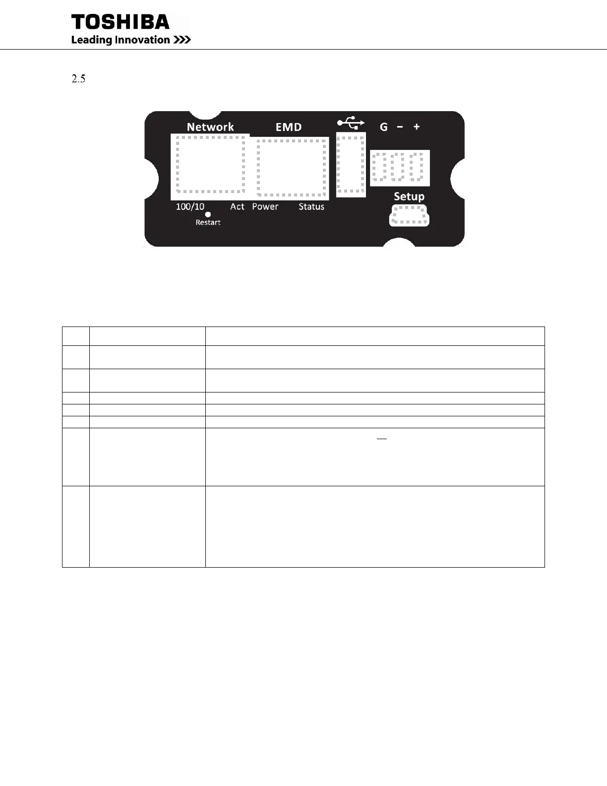
Figure 2-1 RemotEye 4 Faceplate Layout
Table 2-1 RemotEye 4 Connections
Connects to network.
LED indication: LAN 10/100 link, Activity.
Connects to an environmental sensor (EMD)
LED indication: System power, System status.
Phoenix connector for RS-485 serial connections.
Connects to a workstation USB A port with the provided USB adapter cable.
Restart button (Access
through faceplate)
Restarts RemotEye 4 display only. (Does not restart the UPS) (The Restart button
is behind faceplate, under the network port. It can be accessed with a thin probe
inserted through the “Restart” port.)
Press 1 second – Restart RemotEye 4
(This does not affect the operation of UPS.)
Hard Reset button
(Behind faceplate)
The Hard Reset button is located behind the RemotEye 4 faceplate, beneath the
USB port. Remove the faceplate to access the Hard Reset button.
With the faceplate removed and the PCB installed, press and hold the
Hard Reset button for at least 10 seconds.
This will restore the RemotEye 4 parameters to their default values,
including the Username (TOSHIBA) and Password (ADMIN)
See 2.5.1 Hard Reset Button for instructions on accessing the Hard Reset button.
 Loading...