In a multiplex configuration, each VRI-1S3 board is connected to any one of the Device connectors (Device 1-1
through 2-16) on the bright blue controller with TB1 for RS-485 communications and TB2 for power on a VRI-
1S3 in parallel. A maximum of 16 VRI-1S3 boards can be connected to each channel in this manner.
Note: Only identical protocol devices can be connected on the same channel on the bright blue. VRI-1S3
devices cannot be wired on the same data channel with any older Vanderbilt or Schlage devices.
Daisy chain configuration
In a daisy chain configuration, the VRI-1S3 reader interfaces are connected to one another in series. A maximum
of 16 devices can be connected to a bright blue data channel. This configuration is not recommended by
Vanderbilt; if a wire is broken in the loop, downstream devices will not communicate with bright blue.
PIN Functions
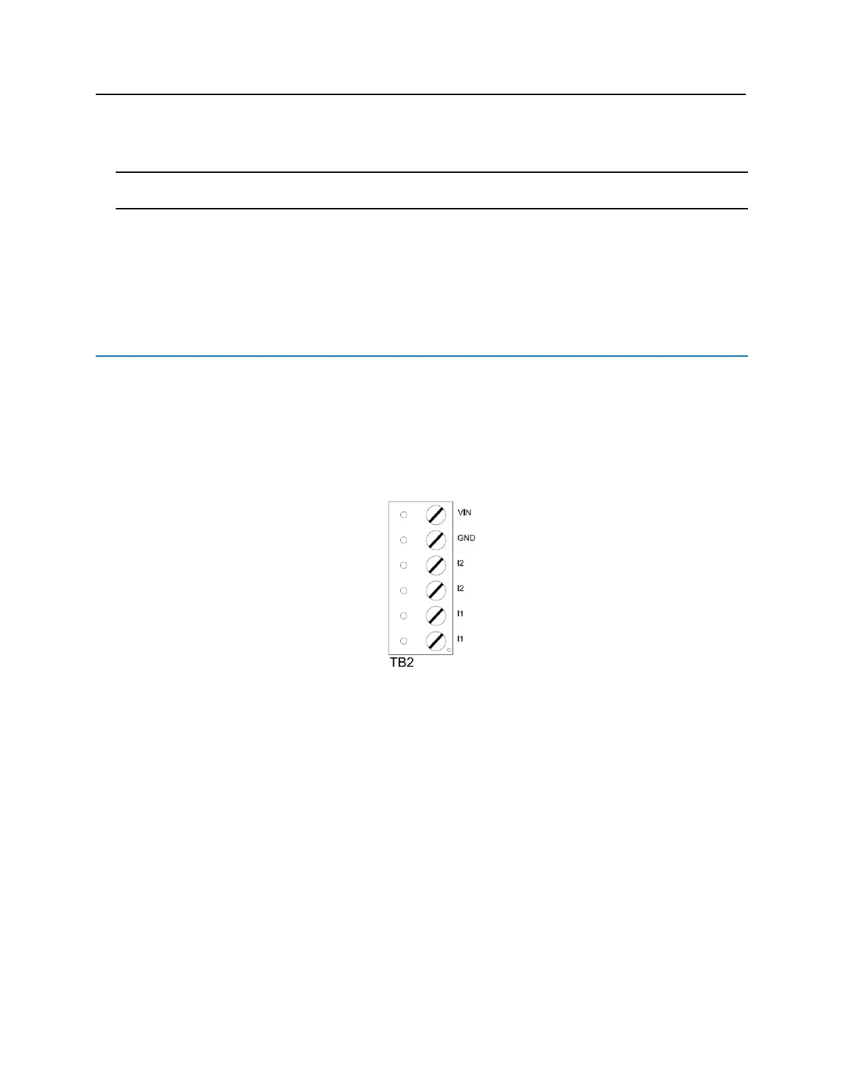
TB2 – Power source and contact inputs
Provides power to the VRI-1S3 from the bright blue. 12 – 24 VDC 10% filtered power required. Two supervised
or unsupervised contact inputs are provided, typically for DOD and REX monitoring. Contact inputs have individual
grounds. Supervised door contacts support a maximum wire length of 1,000 ft. Unsupervised door contacts
support a wire length of 2,000 ft.
▪ PIN 1 is Power (VIN)
▪ PIN 2 is Ground (GND)
▪ PIN 3 is Door Contact 2 (Normally Closed)
▪ PIN 4 is Door Contact 2 (Normally Closed)
▪ PIN 5 is Door Contact 1 (Normally Closed)
▪ PIN 6 is Door Contact 1 (Normally Closed)
J2 – Reader Interface Addressing
The address of the VR-1S3 is dependent on the position of jumpers on these pins. Please see the section on
Addressing VRI-1S3 for more details.
J3 – On Board Tamper Connection
The enclosure tamper switch will be wired to the supplied tamper connector flying leads. Polarity is not a concern.
J4 – RS485 Communication Line Terminator

 Loading...

