Configuration
The VRI-2 will be connected to the bright blue via RS-485 protocol. A maximum of 16 reader interfaces can be
connected to one bright blue data channel. Wire runs are limited to 4,000 feet (Data Only) from the bright blue
to a VRI-2 (see Recommended Wire Chart). Data communication between the bright blue and the reader
interfaces can be a multiplex or a daisy chain configuration.
Multiplex configuration
In a multiplex configuration, each VRI-2 board is connected to any one of the Device connectors (Device 1-1
through 2-16) on the bright blue controller with TB6 for RS-485 communications and TB7 for power on a VRI-2 in
parallel. A maximum of 32 reader interfaces (16 VRI-2 boards if using both reader interfaces) can be connected
in this manner (8 VRI-2 per bright blue data channel).
Note: Only identical protocol devices can be connected on the same channel on the bright blue. VRI-2 devices
cannot be wired on the same data channel with any older Vanderbilt or Schlage devices.
Daisy chain configuration
In a daisy chain configuration, the VRI-2 reader interfaces are connected to one another in series. A maximum of
32 reader interfaces (16 VRI-2 boards if using both reader interfaces) can be connected to a bright blue (8 VRI-2
per bright blue data channel). This configuration is not recommended by Vanderbilt; if a wire is broken in the
loop, downstream devices will not communicate with bright blue.
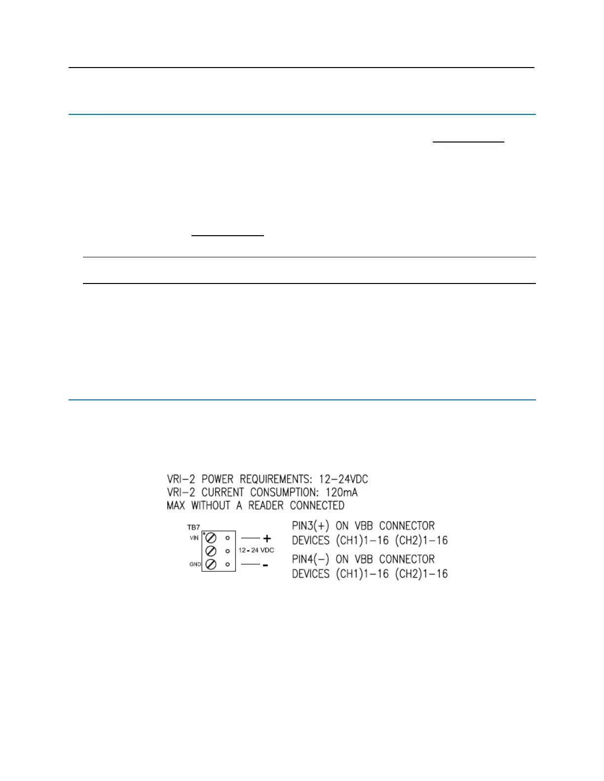
PIN Functions
TB7 - Power source
Provides power to the VRI-2 from the bright blue.
▪ PIN 1 is Power (VIN), 12 – 24 VDC
▪ PIN 2 unused
▪ PIN 3 is Ground (GND)

 Loading...

