Contacts and Pin Functions
A set of input contacts and output relays are provided on the Schlage Adaptable AD-300 Series locks.
Input Contacts
▪ Request to Exit (REX), normally open, non-supervised
▪ Door Open Detect (DOD), normally open, non-supervised
▪ Clutch Position, normally closed, non-supervised
▪ Key Switch, normally closed, non-supervised
▪ Interior Push Button, normally open, non-supervised
▪ Lithium Battery
Credential Reader Technologies
▪ HID Proximity Credential
▪ Magnetic Stripe Credential
J3 & J4 - RS-485 termination. This jumper must be in place to enable communication between the AD300 lock
and bright blue.
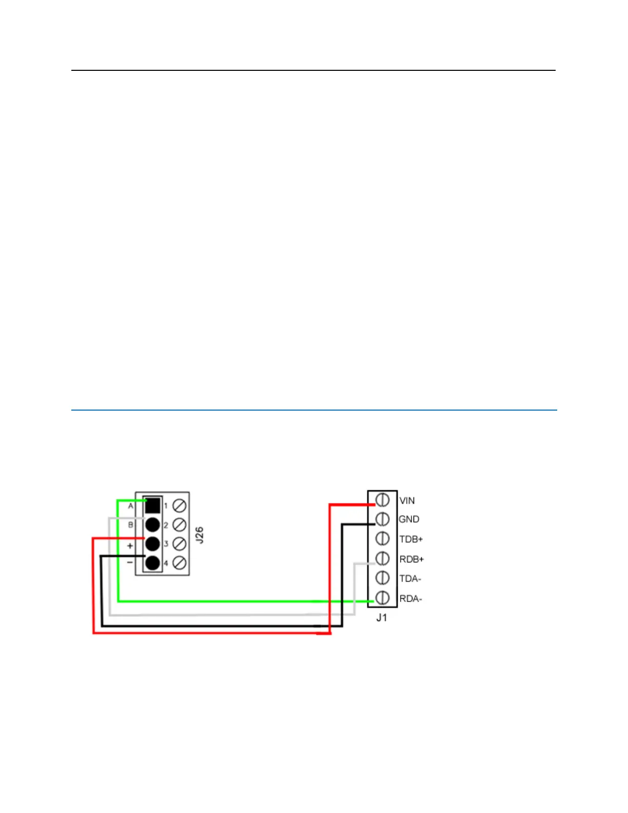
J1 - Power source and communication. Used to connect bright blue to the AD300 lock.
SW1 - Tamper Switch
Connecting to bright blue
Communication between the bright blue controller and an AD-300 lock is via RS-485 protocol. Any one of the
Device connectors (Device 1-1 through 2-16) on the bright blue board can be used to communicate with J1 on
an AD-300 lock. The example below shows using Device 1-1 on the bright blue board and J1 on the AD-300
lock.

 Loading...

