Home
Vanderbilt
Security Sensors
bright blue
Vanderbilt bright blue User Manual
4
of 1
of 1 rating
242 pages
Give review
Manual
Specs
To Next Page
To Next Page
To Previous Page
To Previous Page
Loading...
VBBIM09/33/20 v5.0.3
Chapter 16
VEVMS-VBB Video Ser
ver Integration
231
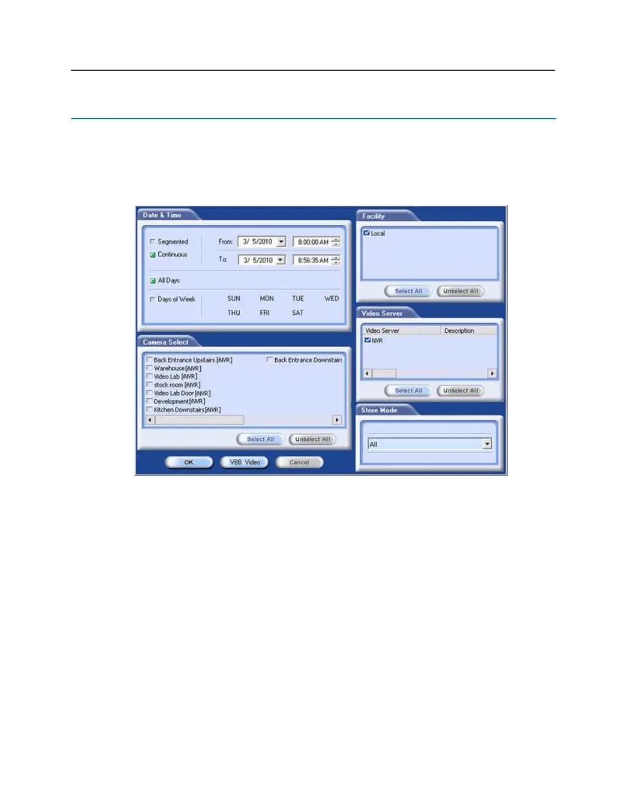
Searching for bright bl
ue Transaction Alarms
Video
can
also
be
searched
through
based
on
bright
bl
ue
tr
ansactions.
This
is
done
through
the
standard
Find
utility in the
Playback
application by following these steps.
1
Select
the
desired
Date
/
Time
range,
Facility,
VEVMS
DVR/NVR
and
Camera(s),
th
en
cl
ick
the
VBB
Video
button.
231
233
Table of Contents
Table of Contents
3
UL Listing Summary
13
Compatible UL Evaluated Equipment
13
Hardware Not UL Evaluated
13
Firmware Designation
14
UL Evaluated Firmware
14
The Following Should be Incorporated into the System
14
Operation Testing and Maintenance
15
Operation Testing
15
Maintenance
15
Declaration of Conformity
16
Preface
17
Who Should Use this Book
17
How this Book Is Organized
17
Symbols and Conventions
18
U.s./International Technical Support
18
Hours of Technical Support
18
Before Installation
19
Requirements
19
Electrical Wiring Considerations
19
Before Powering System
19
Environmental Consideration
20
Cable Requirement Chart
20
Web Browser Requirements
21
Internet Explorer 11
21
Firefox V80.0
21
Apple Safari V13.1 (os X)
21
Apple Safari Mobile
21
Google Chrome V85.0
21
Device Power Requirements
22
Bright Blue
23
Overview
23
Highlights
24
Dimensions
24
Power Supply Requirements
24
Power Method 1 - Single Power Supply
25
Power Method 2 - Multiple Power Supplies
25
Configuration Guidelines
25
Installation and Configuration Steps
25
Enclosure Installation
26
Features
26
Bright Blue Pin Layout
27
Bright Blue Pin Functions
27
Functions on AP02 Controller
30
Bright Blue LED Indicators
31
Bright Blue IP Configuration
31
Static IP Configuration (Recommended)
31
DHCP Configuration
38
Bright Blue Date and Time Setup
40
Using the Bright Blue Software to Set Date and Time
40
Using the Discovery and Configuration Tool to Set Date and Time
44
Battery Replacement
47
Vbb-Ri
48
Overview
48
Highlights
49
Features
49
Specifications
49
VBB-RI Enclosure
50
Features
50
Environmental Conditions
51
Mounting the Enclosure
51
VBB-RI Pin Layout
51
VBB-RI Pin Functions
52
Pins Left at Default
52
Pins Not Used
53
Connecting to Bright Blue
53
Optional - Powering VBB-RI Directly from a Power Supply
54
Addressing the VBB-RI
54
Connecting to Read Head
55
Recommended Wire Chart: VBB-RI to Reader Head
55
P3 - VBB-RI Pin Connections
56
XCEED ID XF 1050 Proximity Reader
56
Magnetic Stripe Reader
57
Installing Diode for Lock Wiring - Relay
57
Vbb-Obri
58
Overview
58
Highlights
59
Features
59
Specifications
59
PIN Layout
60
PIN Functions
60
Reader and I/O Assignment
62
Connecting to Bright Blue
63
Addressing
63
Connecting to Read Heads
63
Recommended Wire Chart
63
PIN Connections
63
Proximity Reader
64
Magnetic Stripe Reader
64
SBB-RI (Legacy)
65
Overview
65
Highlights
66
Standard Features
66
Specifications
66
SBB-RI Enclosure
66
Features
66
Environmental Conditions
67
Mounting
67
SBB-RI Pin Layout
67
SBB-RI Pin Functions
68
Connecting to Bright Blue
69
Optional - Powering SBB-RI Directly from a Power Supply
70
Addressing the SBB-RI
70
Connecting to Read Head
71
Recommended Wire Chart: SBB-RI to Reader Head
71
P3 - SBB-RI Pin Connections
72
XCEED ID XF 1050 Proximity Reader
72
Magnetic Stripe Reader
73
Vbb-Nri
74
Overview
74
Highlights
75
Standard Features
75
Specifications
75
VBB-NRI Enclosure
75
Features
75
Environmental Conditions
76
Mounting
76
VBB-NRI IP Configuration
76
Static IP Configuration (Recommended)
76
DHCP Configuration
81
Configuration GUI (Graphic User Interface)
83
VBB-NRI Pin Layout
85
VBB-NRI Pin Functions
86
Pins Left at Default
87
Pins Not Used
87
Connecting to Bright Blue
88
Connecting to Read Head
89
Recommended Wire Chart: VBB-NRI to Reader Head
89
P2 - VBB-NRI Pin Connections
89
Proximity Reader
90
Magnetic Stripe Reader
90
Installing Diode for Lock Wiring - Relay
91
Upgrading Firmware
91
Verifying Upgrade/Checking Version Number
92
Vbb-Nri G2
94
Overview
94
Highlights
95
Standard Features
95
Specifications
95
VBB-NRI G2 Enclosure
95
Features
95
Environmental Conditions
96
Mounting
96
VBB-NRI G2 IP Configuration
96
Static IP Configuration (Recommended)
96
DHCP Configuration
100
Configuration GUI (Graphic User Interface)
103
VBB-NRI G2 Pin Layout
106
VBB-NRI G2 Pin Functions
106
Factory Reset and Power down
108
Reboot
108
Power down
108
Reboot and Reset to Default IP Address
108
Power down and Reset to Default IP Address
108
Connecting to Bright Blue
109
Connecting to Read Head
110
Recommended Wire Chart: VBB-NRI G2 to Reader Head
110
7 & 9 VBB-NRI G2 PIN Connections
110
Proximity Reader
111
Magnetic Stripe Reader
111
Installing Diode for Lock Wiring - Relay
112
Upgrading Firmware
112
Verifying Upgrade/Checking Version Number
113
Overview
114
Highlights
114
Features
115
Specifications
115
Enclosure
115
Environmental Conditions
116
Mounting the Enclosure
116
PIN Layout
116
Configuration
116
PIN Functions
117
TB2 - Power Source and Contact Inputs
117
J2 - Reader Interface Addressing
117
J3 - on Board Tamper Connection
117
J4 - RS485 Communication Line Terminator
117
D1 (A) / D2 (B) - Status Leds
118
Connecting to Bright Blue
118
Optional - Powering VRI-1 Directly from a Power Supply
119
Addressing
120
Connecting to Read Head
121
Recommended Wire Chart: VRI-1 to Reader Head
121
TB4 - Reader Head Connections
122
XCEED ID XF 1050 Proximity Reader
122
Magnetic Stripe Reader
122
Installing Diode for Lock Wiring - Relay
123
Vri-1S3
124
Overview
124
Highlights
124
Features
125
Specifications
125
Enclosure
125
Environmental Conditions
126
Mounting the Enclosure
126
PIN Layout
126
Configuration
126
PIN Functions
127
TB2 - Power Source and Contact Inputs
127
J2 - Reader Interface Addressing
127
J3 - on Board Tamper Connection
127
J4 - RS485 Communication Line Terminator
127
D1 (A) / D2 (B) - Status Leds
128
Connecting to Bright Blue
128
Optional - Powering Directly from a Power Supply
129
Addressing
130
Connecting to Read Head
131
Recommended Wire Chart: VRI-1S3 to Reader Head
131
TB4 - Reader Head Connections
131
XCEED ID XF 1050 Proximity Reader
132
Magnetic Stripe Reader
132
Installing Diode for Lock Wiring - Relay
133
Vri-2 / Vri-2S3
134
Overview
134
Highlights
134
Features
135
Specifications
135
Enclosure
135
Environmental Conditions
136
Mounting the Enclosure
136
PIN Layout
136
Configuration
137
PIN Functions
137
TB7 - Power Source
137
TB6 - Communications
138
TB1 - TB5 Contact Inputs
138
TB10 - TB12 Relay Outputs
139
J15 - Read Head Voltage Selector
139
S1 -Addressing
140
A - R2 Status Leds
140
Schlage Adaptable AD-300 Series Locks
142
Overview
142
Features
142
Specifications
142
Contacts and Pin Functions
143
Connecting to Bright Blue
143
Addressing the AD-300 Lock
144
To Address the AD-300 Lock
144
Schlage VIP Locks
146
Overview
146
Features
146
Specifications
146
Contacts, Relays, and Pin Functions
147
Connecting to Bright Blue
148
Addressing the VIP Lock
149
Schlage Adaptable AD-400 Series
150
Overview
150
Schlage AD-400 Components
151
Schlage AD-400 Series Wireless Modules
151
Panel Interface Module (PIM400-485-VBB)
151
AD-400 Series Wireless Locks
152
Wri400
154
Wiring Instructions
155
Wiring between Bright Blue and PIM400
155
PIM400 Configuration
156
Log in to SUS
156
Pair to PDA
156
Set PIM400 Address
157
AD-400 Series Lock Configuration
160
Linking/Addressing
160
Diagnostics
161
WRI400 Configuration
163
Connecting to Hhd/Coupling/Linking
163
Additional Configuration
165
Schlage NDE Series Wireless Locks with ENGAGE
169
Overview
169
Schlage NDE Series Components
170
Schlage NDE Series Wireless Modules
170
Gateway (GWE - ENGAGE)
170
NDE Series Wireless Locks
171
GWE - ENGAGE Gateway Wiring Instructions
172
GWE - ENGAGE Gateway, NDE Lock and SMS Addressing
173
Configuring GWE - ENGAGE Gateway and NDE Locks
173
Allegion ENGAGE Account
173
Download ENAGE App
174
Commission / Configure GWE - ENGAGE Gateway
174
Commission NDE Locks W/ ENGAGE Technology
176
Configure Communications Delay and Retry Timing
177
Define ENGAGE Devices in Bright Blue
178
Link NDE Locks to GWE - ENGAGE Gateway
180
Schlage LE Series Wireless Locks
193
Overview
193
Schlage LE Series Components
194
Schlage LE Series Wireless Modules
194
Gateway (GWE - ENGAGE)
194
LE Series Wireless Locks
195
GWE - ENGAGE Gateway Wiring Instructions
197
GWE - ENGAGE Gateway, LE Lock and SMS Addressing
197
Configuring GWE - ENGAGE Gateway and LE Locks
197
Allegion ENGAGE Account
197
Download ENAGE App
198
Commission / Configure GWE - ENGAGE Gateway
198
Commission LE Series Locks
198
Define ENGAGE Devices in Bright Blue
198
Link LE Locks to GWE - ENGAGE Gateway
198
Schlage Wireless Readers
205
Overview
205
Abbreviations
206
Schlage Wireless System Components
206
Wireless Panel Interface Module - PIM-SBB (Legacy)
207
Schlage Wireless Modules
208
WA Series Locks (WA)
208
Wireless Reader Interface (WRI - Indoor or Outdoor)
210
Wiring Instructions
211
Wiring between Bright Blue and PIM Module
212
Wireless Reader Modules Configuration
213
Device Capacities
213
Linking and Addressing Locks to the PIM
213
Installing the CDT Software
214
Installing Microsoft Java Virtual Machine
214
Internet Options
215
Configuring PIM
215
Configuring the WRI
218
Configuring WA Series Locks
219
VEVMS-VBB Video Server Integration
221
Overview
221
Cameras
222
Configuration
223
Viewing Bright Blue Transaction Alarms
229
Searching for Bright Blue Transaction Alarms
232
Troubleshooting
235
Overview
235
Device Communication
235
Device Addressing Issues
235
Wiring Problems
235
Upgrading Software
236
Manually Unlock Doors for Upgrade
236
Disable Encryption
236
File Not Authorized Warning While Upgrading
236
System Reboot
236
Discovery and Configuration Tool
236
Errors When Logging in or Saving Records to the Database
236
Date and Time
237
Incorrect Date/Time
237
Slowly Losing/Gaining Time
237
4
Based on 1 rating
Ask a question
Give review
Questions and Answers:
Need help?
Do you have a question about the Vanderbilt bright blue and is the answer not in the manual?
Ask a question
Vanderbilt bright blue Specifications
General
Brand
Vanderbilt
Model
bright blue
Category
Security Sensors
Language
English
Related product manuals
Vanderbilt GM730
6 pages
Vanderbilt GM7 Series
66 pages
Vanderbilt PDM-I12T
5 pages
Vanderbilt GM760
66 pages

 Loading...

