116
positioning time is shortened. At this time, the response of the servo system depends on this parameter,
not P1-02 (position loop gain). The gain of the model loop is only valid in position mode.
6.7 Vibration suppression
6.7.1 Overview
The mechanical system has a certain resonance frequency. When the servo gain is increased, the
continuous vibration may occur near the resonance frequency of the mechanical system. Generally in
the range of 400Hz to 1000Hz, it caused the gain can not continue to increase. Vibration can be
eliminated by automatically detecting or manually setting the vibration frequency. After the vibration is
eliminated, if the responsiveness needs to be improved, the gain can be further improved.
Note:
(1) Servo responsiveness will change after vibration suppression operation.
(2) Before performing the vibration suppression operation, please set the inertia ratio and gain
parameters correctly, otherwise it can not be controlled properly.
6.7.2 Operation tools
XinJeServo Mechanical
Characteristic Analysis
6.7.4 Vibration
Suppression (PC
Software)
All versions of PC
software support
Panel vibration
suppression
6.7.3 Vibration
Suppression
(Panel)
Driver firmware
requires version
3700 or higher
XinJeServo Mechanical
Characteristic Analysis
6.7.4 Vibration
Suppression (PC
Software)
All versions of PC
software support
Note: The firmware version of the drive is viewed through U2-07.
6.7.3 Vibration suppression(panel)
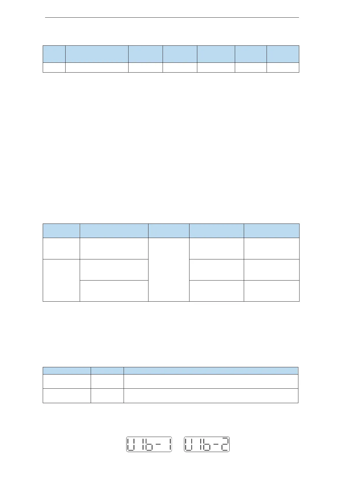
There are two modes of panel vibration suppression, mode 1(vib-1) and mode 2(vib-2).
Difference between Two Kinds of Vibration Suppression
Only the parameters related to vibration suppression will be
changed.
It will change the parameters of vibration suppression and the gain
of speed loop.
The operation steps:
1. Enter F0-10 in auto-tuning mode, the panel shows vib-1 or enter F0-11, the panel shows
vib-2;
or
 Loading...


