26
3.2 Classification and function of signal terminals
3.2.1 Pulse signal
The input signal + of open collector (24V voltage) is P+24V/D+24V.
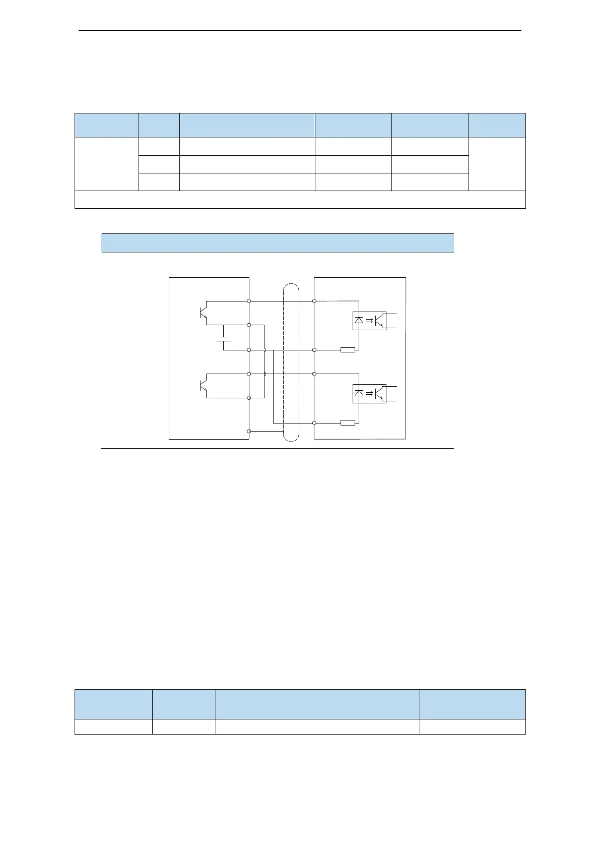
The interface circuit of P+D, CW, CCW:
Open collector (24V voltage)
PLC, CNC and SCM servo driver
Note:
(1) The supply voltage range of P-/P+24V and D-/D+24V is 18V~25V. If it is below 18V, there may be
pulse and direction anomalies.
(2) In order to resist interference, twisted-pair shielding wire must be used.
(3) Servo pulse input port will turn on for 10 mA.
(4) If the controller is XINJE PLC, the rated current of the output port of the pulse is 50mA. According
to this data, theoretically a single pulse can drive at most five servos. No more than three are
recommended.
3.2.2 SI input signal
Please use a relay or an open collector transistor circuit to connect. When using relay connection,
please select the relay for small current. If the relay is not small current, it will cause bad contact.
Multifunctional input signal terminal
 Loading...


