Basic Programming 5 - 13
This parameter is only available in the V/F or V/F with PG control methods (A1-02 = 0 or 1).
The Drive operates utilizing a set V/F pattern to determine the appropriate output voltage level for each commanded speed.
There are 15 different preset V/F patterns to select from (E1-03 = 0 to E) with varying voltage profiles, base level
(base level = frequency at which maximum voltage is reached), and maximum frequencies.
There are also settings for Custom V/F patterns that will use the settings of parameters E1-04 through E1-13. E1-03 = F selects
a custom V/F pattern with an upper voltage limit and E1-03 = FF selects a custom V/F pattern without an upper voltage limit.
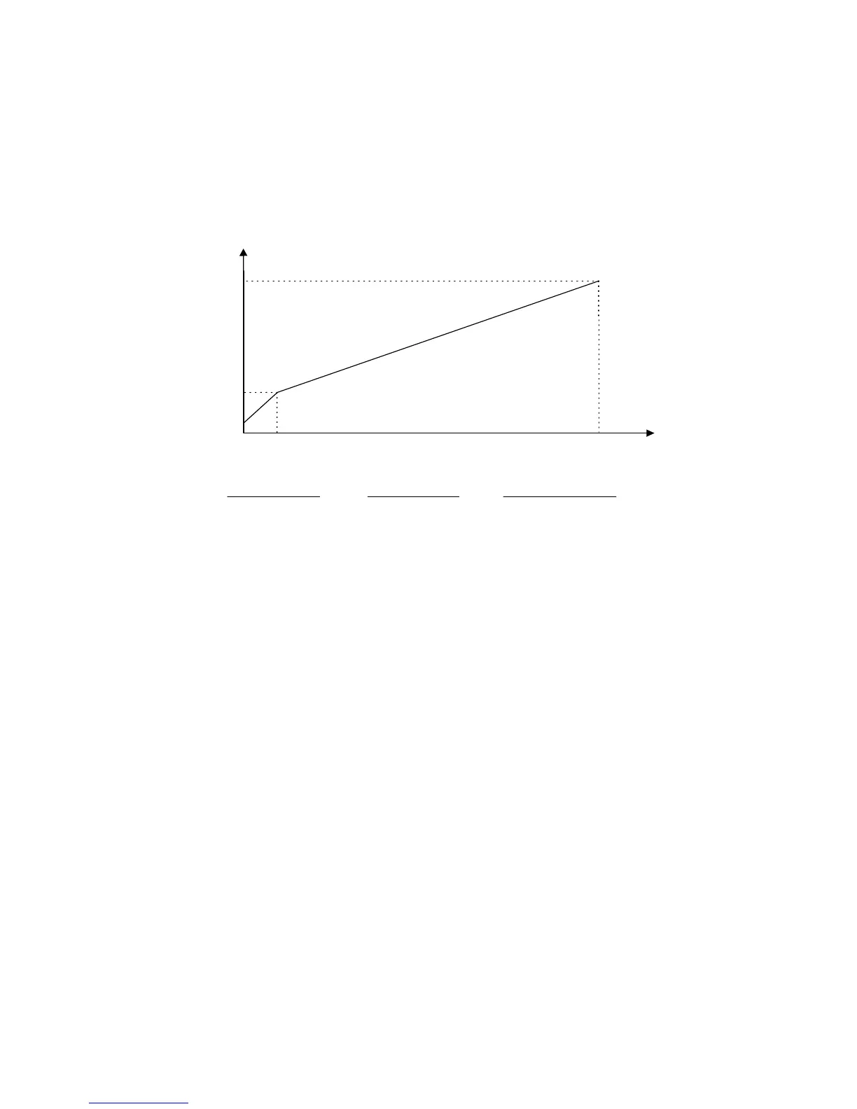
See Fig 5.8 below for the upper voltage limit.
Fig 5.8 V/F Pattern Voltage Upper Limit
E1-06 / 40 E1-06
250V
Output Voltage
Output Frequency
B
A
F7U20P4-23P7 F7U24P0-2045 F7U2055 & higher
A = 5V A = 2.5V A = 2.5V
B = 35V B = 20V B = 15V
For 480V class Drives, the values are twice that of 208-240V class Drives.
Voltage Upper Limits for 208-240V Class Drives
Email: Sales@aotewell.com
 Loading...