Electrical Installation 2 - 36
PG-D2
The terminal specifications for the PG-D2 are given in Table 2.20.
Wiring the PG-D2
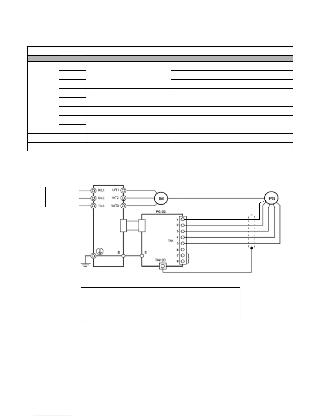
Wiring examples are provided in Fig 2.21 for the PG-D2.
Fig 2.21 PG-D2 Wiring
Table 2.20 PG-D2 Terminal Specifications
Terminal No. Contents Specifications
TA1
1
Power supply for pulse generator
12Vdc (±5%), 200mA max.*
2 0Vdc (GND for power supply)
3 5Vdc (±5%), 200mA max.*
4
Pulse input terminals
Line driver input (RS-422 level)
Maximum response frequency: 300kHz
5
6 Common terminal -
7
Pulse monitor output terminals Line driver output (RS-422 level)
8
TA2 (E) Shield connection terminal -
* 5Vdc and 12Vdc cannot be used at the same time.
Drive
Power supply 0Vdc
Power supply +5Vdc
Pulse input + (A phase)
Pulse input - (A phase)
Pulse monitor output
R/L1
S/L2
T/L3
Branch
Circuit
Protection
Power supply +12Vdc
4CN
4CN
•Shielded twisted-pair wires must be used for signal lines.
•Do not use the PG-D2's power supply for anything other than the pulse generator (encoder).
Using it for another purpose can cause malfunctions due to noise.
•The length of the pulse generator's wiring must not be more than 100 meters.
Email: Sales@aotewell.com
 Loading...