Electrical Installation 2 - 39
Wiring the PG-W2
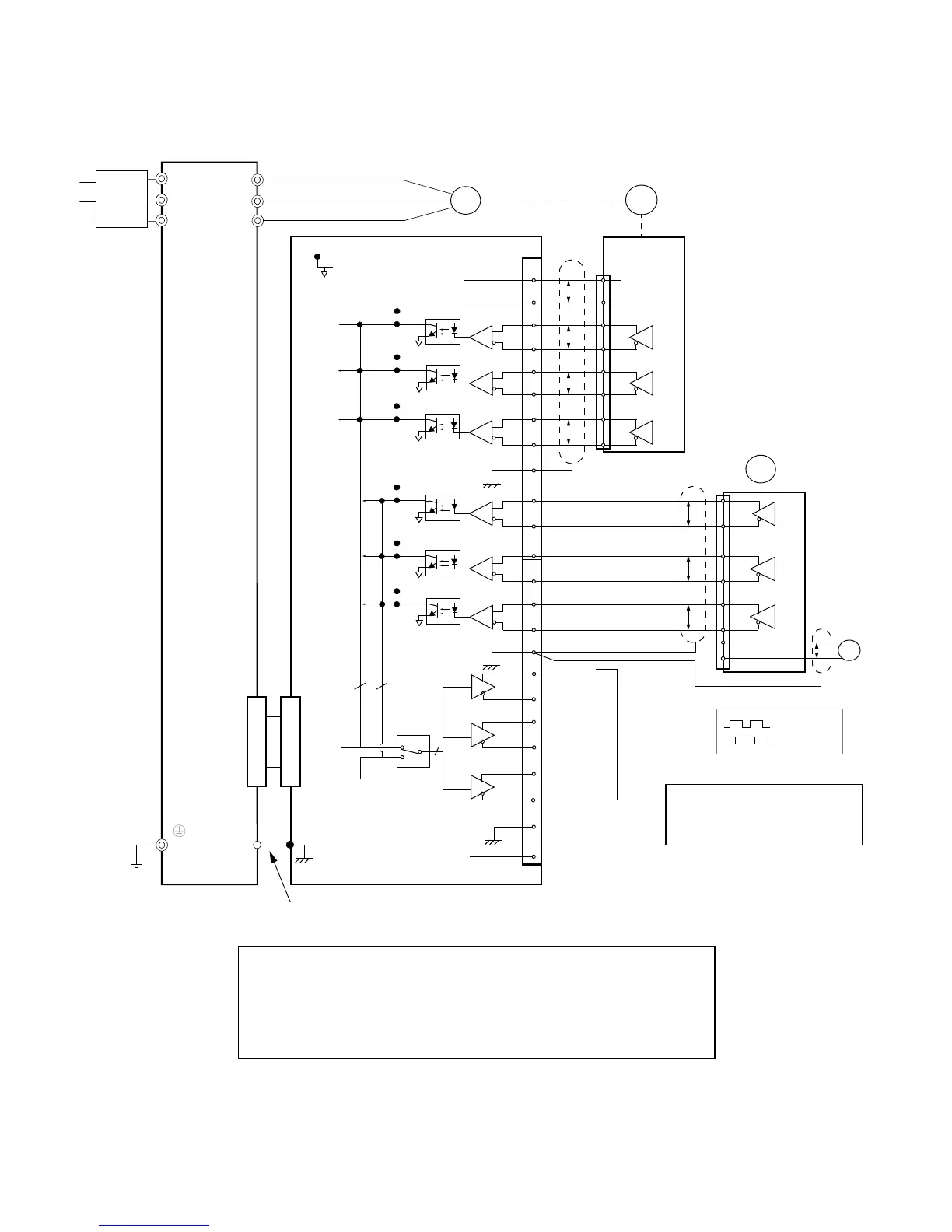
Wiring examples are provided in Fig 2.23 for the PG-W2.
Fig 2.23 PG-W2 Wiring
R/L1
S/L2
T/L3
M
U/T1
V/T2
W/T3
Drive
PG-1
1
2
3
4
5
6
7
8
9
10
11
12
13
14
15
16
17
18
19
20
21
22
23
24
IP12
*
IG12
(+12V)
(0V)
12V
0V
P
P
P
P
P
P
P
TP1
(E)
12V
0V
P
+
Pulse A
Pulse B
Pulse Z
Pulse
IG5
(0V)
PG-2
4CN4CN
12
TP3
TP7
TP6
TP5
TP4
TP8
3
Pulse
Out 1
3
Pulse A1
Pulse B1
Pulse Z1
Pulse A2
Pulse B2
Pulse Z2
TP2
Notes:
* Power supply for PG-1 (from PG-W2).
** PG-2 requires external power supply.
Pulse A
Pulse B
Ground wire
**
3
Pulse
Out 2
(E)
-
12V
Monitor
Outputs
(E)
(E)
PG-W2
Branch
Circuit
Protection
•Shielded twisted-pair wires must be used for signal lines.
•Do not use the PG-W2's power supply for anything other than the pulse generator (encoder).
Using it for another purpose can cause malfunctions due to noise.
•The length of the pulse generator's wiring must not be more than 100 meters.
•Do not use PG-W2 to supply both PG units.
Email: Sales@aotewell.com
 Loading...