Physical Installation 1 - 5
Component Names
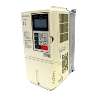
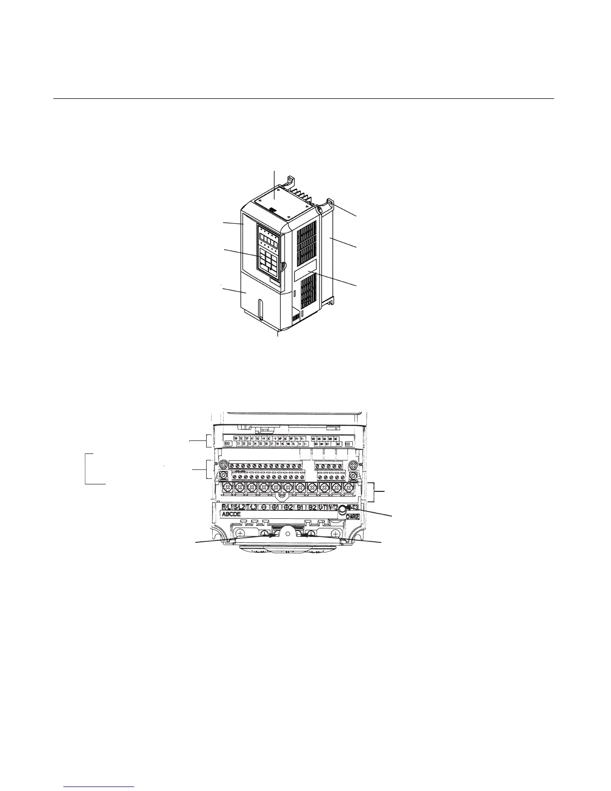
Models CIMR-F7U20P4 thru 2018 and 40P4 thru 4018
The external appearance, component names, and terminal arrangement of the Drive are shown in Fig 1.4 and 1.5.
Fig 1.4 Drive Appearance
Fig 1.5 Terminal Arrangement (Terminal Cover Removed)
Top protective cover
[Required for NEMA Type 1 (IEC IP20)]
Front cover
Digital Operator
Terminal cover
Mounting hole
Die-cast Heat Sink
Nameplate
Bottom protective cover
Ground terminal
Control circuit terminal
layout label
Cont
See Fig. 2.3 for actual
terminal layout
rol circuit terminals
{
Main circuit terminals
Charge indicator
Ground terminal
Email: Sales@aotewell.com
 Loading...