Diagnostics & Troubleshooting 6 - 28
Main Circuit Test Procedure
Before attempting any troubleshooting checks, make sure that the three-phase power is disconnected and locked out. With
power removed from the unit, the DC bus capacitors will stay charged for several minutes. The Charge LED in the Drive will
glow red until the DC bus voltage is below 10Vdc. To ensure that the DC bus is completely discharged, measure between the
positive and negative bus with a DC voltmeter set to the highest scale.
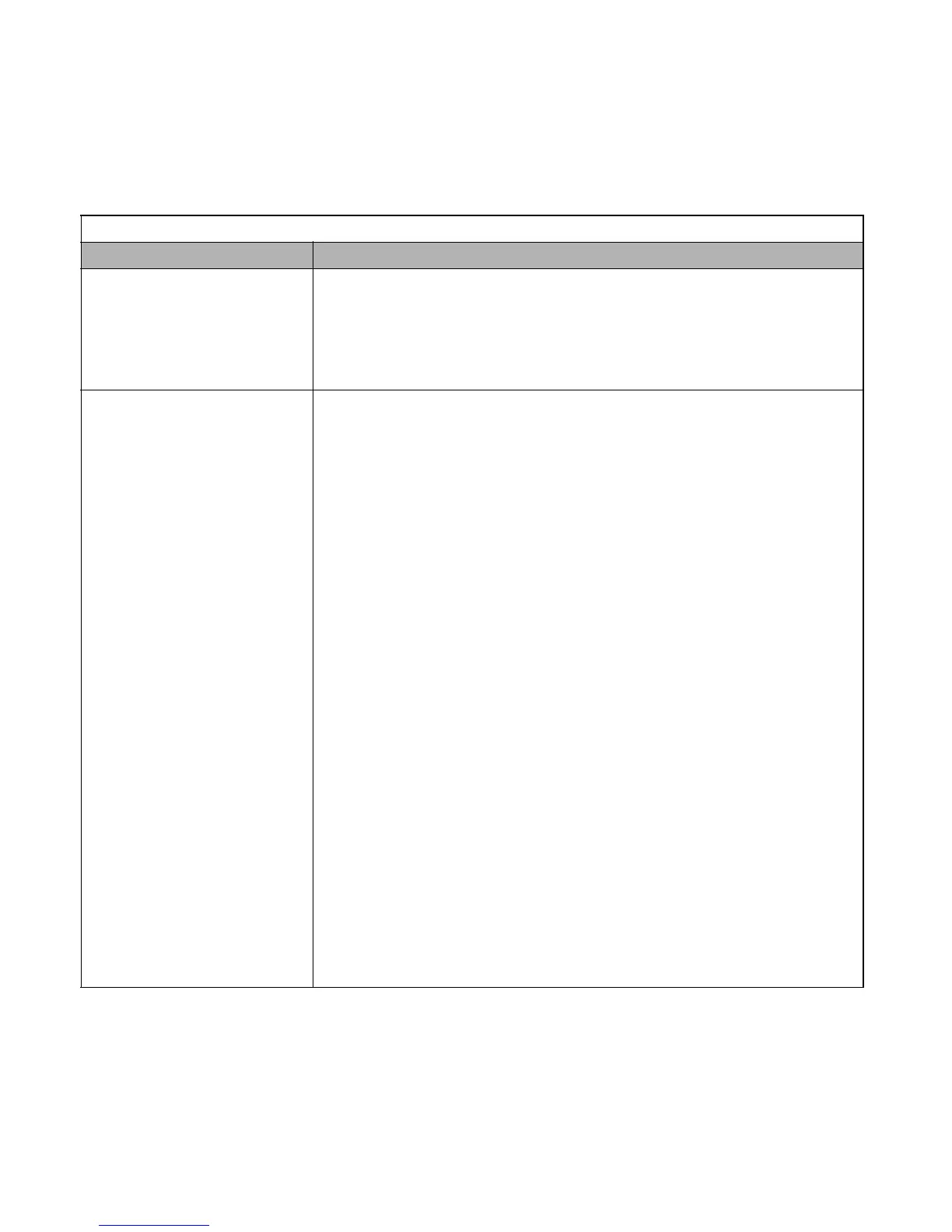
Table 6.6 Main Circuit Test Procedure
Check Procedure
Measure DC Bus Voltage
1. Set the digital multi-meter to its highest Vdc scale.
2. Measure between ⊕ 1 and (-) for the following check:
Place the positive (red) meter lead on ⊕ 1.
Place the negative (black) meter lead on (-).
3. If the measured voltage is < 10Vdc, it is safe to work inside the Drive.
If not, wait until the DC Bus has completely discharged.
Input Diodes
(D1-D12 or Q1)
The input diodes rectify or transform the three-phase input AC voltage into a DC voltage.
1. Set a digital multi-meter to the Diode Check setting.
2. Place the positive (red) meter lead on terminal R/L1.
Place the negative (black) meter lead on terminal ⊕ 1.
Expected reading is about 0.5Vdc.
3. Place the positive (red) meter lead on terminal S/L2.
Place the negative (black) meter lead on terminal ⊕ 1.
Expected reading is about 0.5Vdc.
4. Place the positive (red) meter lead on terminal T/L3.
Place the negative (black) meter lead on terminal ⊕ 1.
Expected reading is about 0.5Vdc.
5. Place the positive (red) meter lead on terminal R/L1.
Place the negative (black) meter lead on terminal (-).
Expected reading is OL displayed.
6. Place the positive (red) meter lead on terminal S/L2.
Place the negative (black) meter lead on terminal (-).
Expected reading is OL displayed.
7. Place the positive (red) meter lead on terminal T/L3.
Place the negative (black) meter lead on terminal (-).
Expected reading is OL displayed.
8. Place the positive (red) meter lead on terminal (-).
Place the negative (black) meter lead on terminal R/L1.
Expected reading is about 0.5Vdc.
9. Place the positive (red) meter lead on terminal (-).
Place the negative (black) meter lead on terminal S/L2.
Expected reading is about 0.5Vdc.
10. Place the positive (red) meter lead on terminal (-).
Place the negative (black) meter lead on terminal T/L3.
Expected reading is about 0.5Vdc.
11. Place the positive (red) meter lead on terminal ⊕ 1.
Place the negative (black) meter lead on terminal R/L1.
Expected reading is OL displayed.
Email: Sales@aotewell.com
 Loading...