Electrical Installation 2 - 2
Terminal Block Configuration
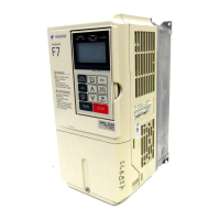
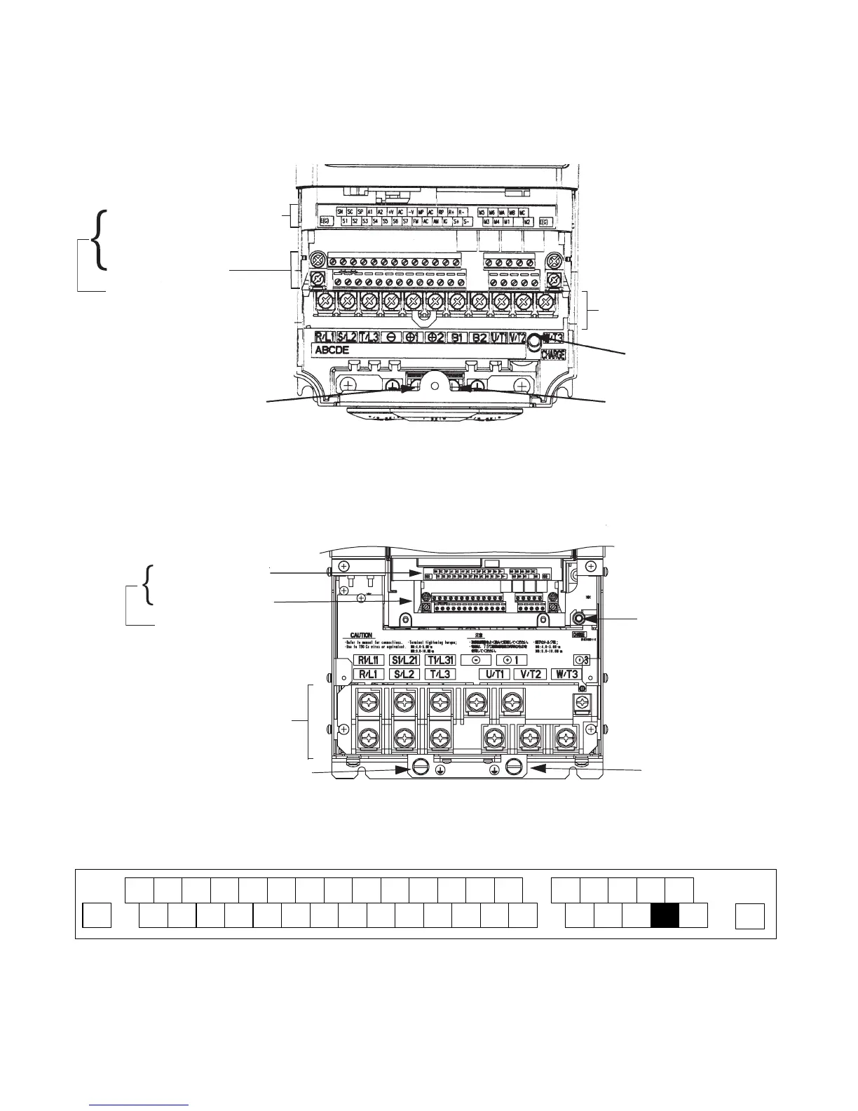
The wiring terminals are shown in Fig 2.1, Fig 2.2 and Fig 2.3.
Fig 2.1 Terminal Configuration for Models CIMR-F7U2018/4018 and Smaller
Fig 2.2 Terminal Configuration for Models CIMR-F7U2022/4022 and Larger
Fig 2.3 Control Circuit Terminal Layout
Ground terminal
Control circuit terminal layout label
Charge indicator
Ground terminal
Main circuit terminals
Ground terminal
Control circuit terminals
See Fig. 2.3 below for
actual terminal layout
Charge indicator
Control circuit terminal
Ground terminal
Main circuit terminals
Ground terminal
layout label
Control circuit terminals
See Fig. 2.3 below for
actual terminal layout
SN SC SP A1 A2 +V AC -V A3 MP AC RP R+ R- MCM5 M6 MA MB
S1 S2 S3 S4 S5 S6 S7 S8 FM AC AM IG S+ S- M2M3 M4 M1
E(G)
E(G)
Email: Sales@aotewell.com
 Loading...