Electrical Installation 2 - 40
Wiring Terminal Blocks
Wire Sizes (Same for All Models)
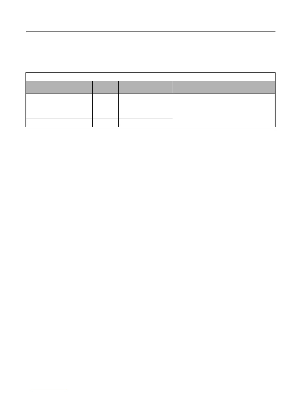
Terminal wire sizes are shown in Table 2.23.
Wiring Method and Precautions
Observe the following precautions when wiring.
• Separate the control signal lines for the PG (Encoder) Feedback Board from main circuit lines and power lines.
• Connect the shield when connecting a PG (Encoder). The shield must be connected to prevent operational errors
caused by noise. Also, do not use any lines that are more than 100m long. Refer to Fig 2.12 for details on
connecting the shield.
• Do not solder the ends of wires. Doing so may cause contact faults.
• When straight solderless terminals are not used, strip the wires to a length of approximately 5.5mm.
• Use shielded, twisted-pair wires for pulse inputs and pulse output monitor wires, and connect the shield to the shield
connection terminal.
Table 2.23 Wire Sizes
Terminal
Terminal
Screws
Wire Thickness
AWG (mm
2
)
Wire Type
Pulse generator power supply
Pulse input terminal
Pulse monitor output terminal
-
Stranded wire:
24 to 17 (0.2 to 1.0)
Single wire:
24 to 17 (0.2 to 1.0)
• Shielded, twisted-pair wire
• Shielded, polyethylene-covered, vinyl sheath cable
• Belden 9504, Hitachi KPEV-S, or equivalent
Shield connection terminal M3.5 20 to 16 (0.5 to 1.3)
Email: Sales@aotewell.com
 Loading...