77
TRANSPORTATION USE
E304 E305 E306
AUTOMATIC MOUTH OF THE MULTI-
STAGE HITCH CBM
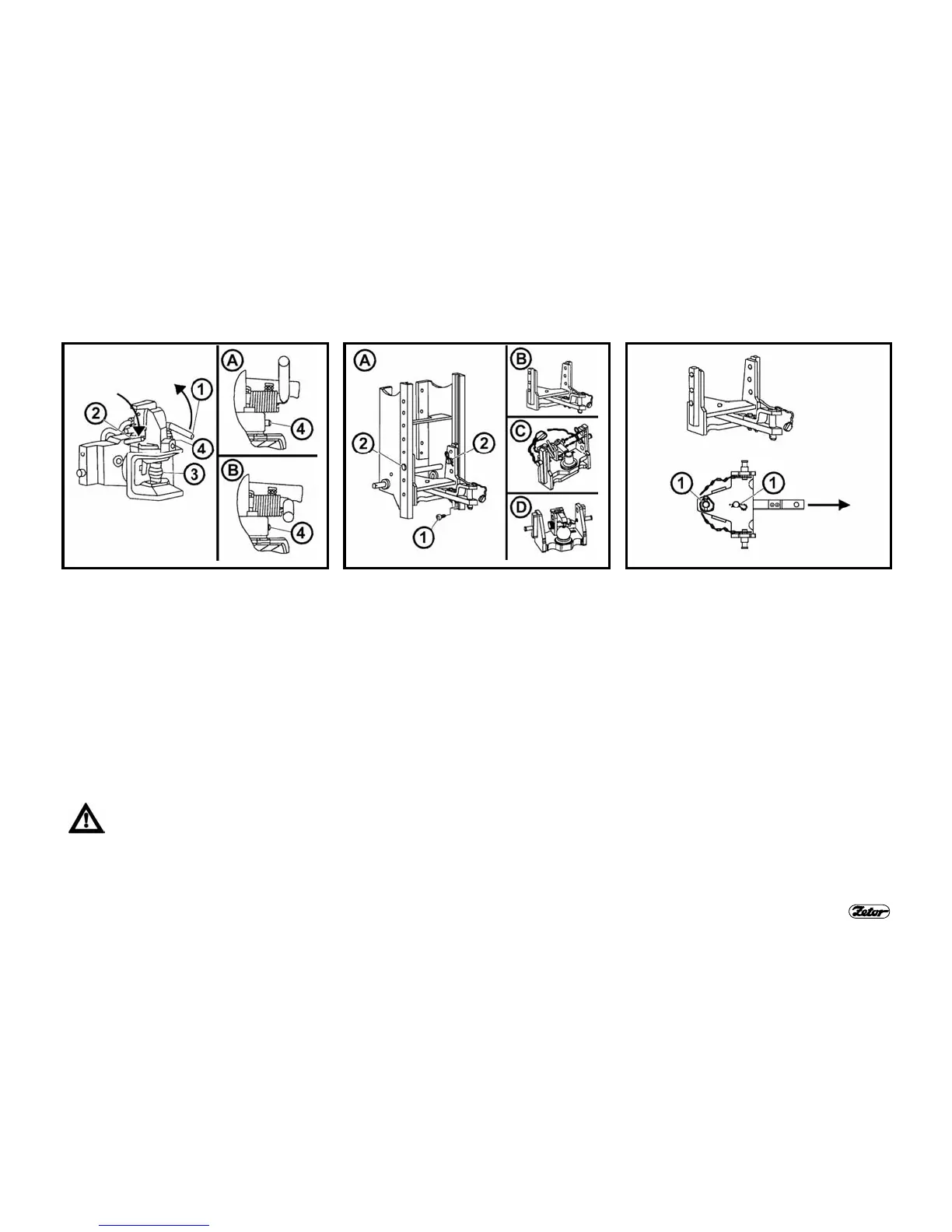
Move the lever (1) in the arrow direction
to engage the pin (3) into the upper posi-
tion, which is indicated by the slided-out
warning indicator (4) - see Fig. (A).
After the mouth seats on the tow ring,
the pin will automatically slide into ring of
the trailer to be coupled. The hitch pin (3)
can be lowered manually by moving the
lever (2) in the arrow direction. The
slided-in warning indicator (4) indicates
the pin inserting in place - see Fig. (B).
Remember to make sure whether
the warning indicator is slided in
always after the trailer attach-
ment as per Fig. (B).
MODULAR SYSTEM OF TRAILER AND
SEMI-TRAILER HITCHES
Types of modules:
Fig. (B) - swinging draw bar bracket
Fig. (C) - swinging draw bar bracket c/w
fixed pintle
Fig. (D) - bracket c/w ø 80 ball
Removal - Fig. (A):
1. Unscrew the locking bolt (1).
2. Secure the module against fall,
unlock and remove pins (2).
3. Move the module down out of the
bracket.
Installation is a reverse procedure to
removal.
SWINGING DRAW BAR BRACKET
MODULE
The swinging draw bar bracket module is
situated in the multi-stage hitch bracket.
SWINGING DRAW BAR
Removal:
1. Unlock and remove pins (1).
2. Move the swinging draw bar out in
the arrow direction.
Installation is a reverse procedure to
removal.
 Loading...