ELECTRICAL INSTALLATION
PRODUCT
ACS6000
DOCUMENT KIND
User manual
DOCUMENT ID.
3BHS212794 E01
REV.
N
LANG.
en
PAGE
122/266
6.4.1. Optical fiber cables
6.4.1.1. Installing the standard optical fibers
1. Pull all cables through the cable duct (3) at the top of the cabinets.
NOTE – Cut-outs in the ducts provide entry into the cabinets.
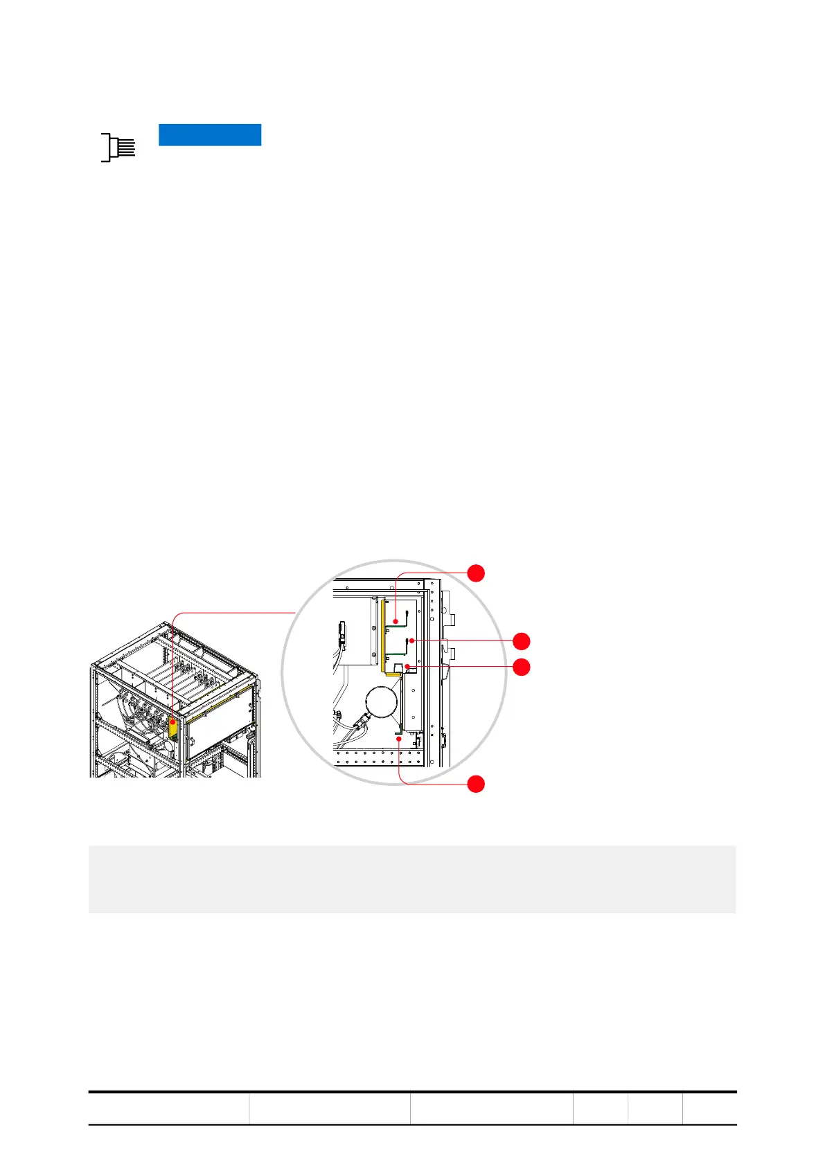
Figure 6-5 Cable tray and cable ducts in an LSU (A = front)
2. Lay the cables into their designated trays and cable ducts as seen in Fig. 6-5.
NOTE – When fastening IGCT power supply cables on the rail for IGCT power
supply cables of RBU, BCU and VLU, make sure that the cables are at a minimum
distance of 5 mm from the closest metal part.
3. Connect all cables and wires according to the “Converter Hardware” diagram.
NOTICE Risk of equipment failure!
Handle optical fibers with care. A damaged or incorrectly installed optical
fiber cable can degrade data transmission and cause equipment failure.
– Only use the designated encoder cable conduit that passes through
the drive to the EXU.
The conduit extends 10 – 20 mm from the entry plate of the drive.
– Cover the cable end with a cap BEFORE you pull the cable through
the conduit.
– DO NOT exceed the maximum tensile load of 1.0 N and the minimum
bend radius of 25 mm.
– When you tighten the cable ties DO NOT deform the optical fibers and
DO NOT use a cable tie gun.
– Hold the connector when you connect or disconnect an optical fiber.
1) Cable tray for auxiliary power supply cable
2) Cable tray for control cables
3) Cable duct for optical fibers
4) Rail for IGCT power supply cables of RBU,
BCU and VLU
2
3

 Loading...


