PREVENTIVE AND CORRECTIVE MAINTENANCE
PRODUCT
ACS6000
DOCUMENT KIND
User manual
DOCUMENT ID.
3BHS212794 E01
REV.
N
LANG.
en
PAGE
233/266
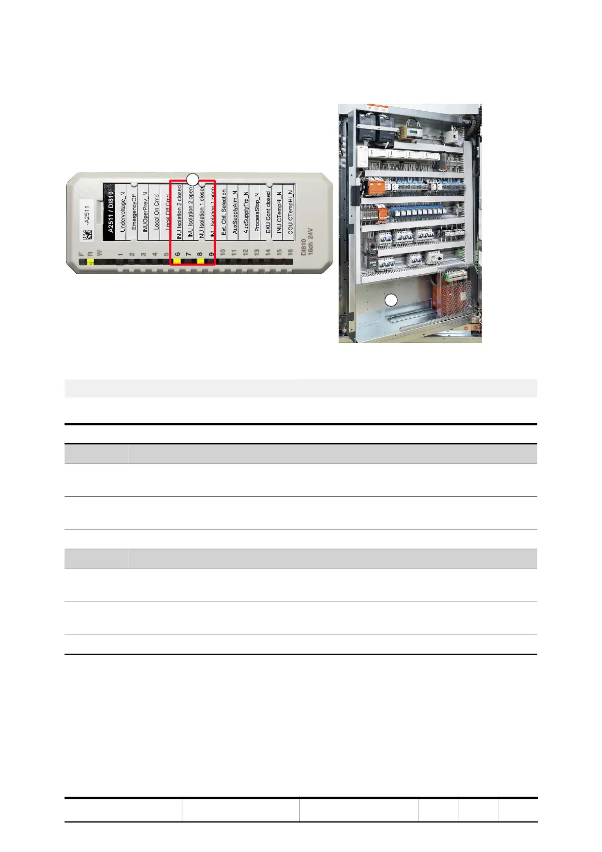
The LEDs of input module A2511 inside COU1 indicate whether the busbar
connectors are fitted or not.
Figure 10-17 Input module A2511
Table 10-1 Description of LEDs on input module A2511
1) Location of LEDs 6 - 9 2) COU1
LED LED Description
6 7
ON OFF The three busbar connectors are fitted in COU1.
The motor is connected to INU2.
OFF ON The three busbar connectors are not fitted in COU1.
The motor is disconnected from INU2.
OFF OFF Invalid configuration. Drive will not start.
8 9
ON OFF The three busbar connectors are fitted in TEU1.
The motor is connected to INU1.
OFF ON The three busbar connectors are not fitted in TEU1.
The motor is disconnected from INU1.
OFF OFF Invalid configuration. Drive will not start.
1
2
 Loading...


