PREVENTIVE AND CORRECTIVE MAINTENANCE
PRODUCT
ACS6000
DOCUMENT KIND
User manual
DOCUMENT ID.
3BHS212794 E01
REV.
N
LANG.
en
PAGE
229/266
4. When the door is open, turn the release dial to the locked position.
5. Tighten the locking screw.
6. Seal the locking screw.
7. Refit the screw cap.
8. To ground the drive, continue with “10.4.8 Connecting a grounding set”
on page 229.
10.4.8. Connecting a grounding set
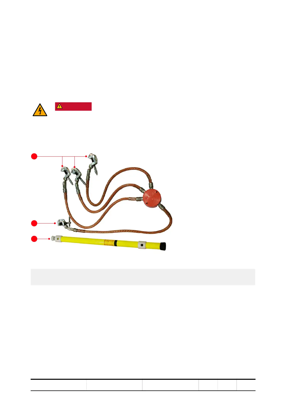
Figure 10-13 Four-way grounding set
Depending on the type of line-side rectifier, continue with:
– “10.4.8.1 Drives with LSU” on page 230
– “10.4.8.2 Drives with ARU” on page 231
DANGER Hazardous voltages!
Grounding equipment ensures that FATAL voltages cannot be fed into the
drive from the main power supply or the motor during maintenance work,
eg, the removal of phase modules.
– Connect grounding equipment at the designated locations.
1) Busbar ground clamps
2) Enclosure ground clamp
3) Telescopic insulating pole
1
2
 Loading...


