ELECTRICAL INSTALLATION
PRODUCT
ACS6000
DOCUMENT KIND
User manual
DOCUMENT ID.
3BHS212794 E01
REV.
N
LANG.
en
PAGE
148/266
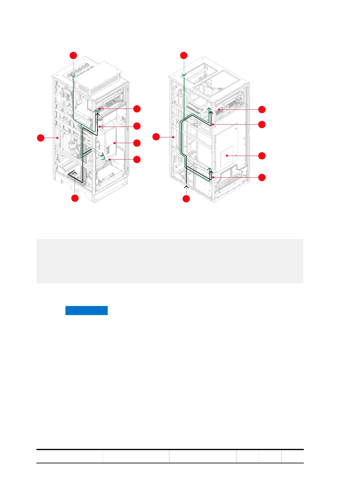
3. Route the cables through the designated cable ducts as illustrated.
Figure 6-36 Cable routing examples in an EXU cabinet with an ED5V, EB5R, EB5S,
EB7P and EB7Q type DCS800 converter (A) and in an EXU cabinet with an ED7Y type
DCS800 converter
6.8.7.2. Optical fiber cables
1) Cable enters through roof
2) PE ground busbar
3) Cable enters through the floor
4) Terminal strip for auxiliary power and
control cables
5) Auxiliary supply cable
6) Terminal for optical fibers behind cover
7) Optical fibers to DCS800 D4 converter
8) Optical fibers to DCS800 D5 converter
NOTICE Risk of equipment failure!
Handle optical fibers with care. A damaged or incorrectly installed optical
fiber cable can degrade data transmission and cause equipment failure.
– Only use the designated encoder cable conduit that passes through
the drive to the EXU.
The conduit extends 10 – 20 mm from the entry plate of the drive.
– Cover the cable end with a cap BEFORE you pull the cable through
the conduit.
– DO NOT exceed the maximum tensile load of 1.0 N and the minimum
bend radius of 25 mm.
– When you tighten the cable ties DO NOT deform the optical fibers and
DO NOT use a cable tie gun.
– Hold the connector when you connect or disconnect an optical fiber.
4
7