POWER ELECTRONICS AND CABINET FEATURES
PRODUCT
ACS6000
DOCUMENT KIND
User manual
DOCUMENT ID.
3BHS212794 E01
REV.
N
LANG.
en
PAGE
75/266
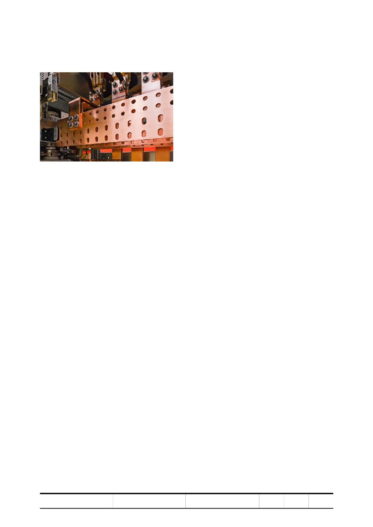
3.8. Busbars and grounding
The drive contains busbars for various types of connections.
Figure 3-32 Busbars
3.8.1. AC busbars
The incoming feeder and motor cables are connected to their corresponding
busbars inside a TEU. In multi-motor drives, several TEUs are part of the
drive lineup.
Depending on drive configuration, the incoming busbars are interconnected with
the ARU or the LSU. The outgoing busbars are interconnected with the inverter
unit(s). Phase designations help identifying the busbars.
3.8.2. DC busbars
The DC busbars connect the ARU or the LSU with INU(s) and CBU. A multi-motor
configuration, can have up to four DC busbar arrangements. The busbars are
mounted in the upper part of the drive and are marked with DC (+), DC (-) and DC
(neutral point).
3.8.3. PE busbar
To maintain safety and to ensure smooth functioning of the equipment, it is
important to ground the drive properly. For this reason, the ground cable of the
drive is connected to the grounding system of the installation site.
The drive is equipped with a continuous PE ground busbar that stretches across
the bottom part of the entire cabinet.
3.8.4. PG busbar
To ensure proper operation, cable shields are connected to the PG ground busbar.
The PE and PG busbar connect inside the capacitor bank unit, which has the
grounding switch on the front door. The connection is made in the factory.