Chapter 5
Programming Parameters
5–2
Engineering Units – A label given to parameter data which specifies
what units are to be used to display the parameter value on the
Programming Terminal. Examples of engineering units include: RPM,
% etc.
Non–Volatile Memory – Data memory in the drive which retains the
values of all data even when power is disconnected from the drive
control. BRAM (Battery Backed Random Access Memory) chips are
used for the non–volatile memory to store some of the drive parameters.
Parameter Table – Table of parameter entries for all configuration and
setup parameters used in the drive.
Parameter Entry – Information stored in the drive which contains the
parameter number, parameter data and all other information related to the
specific parameter.
Parameter – Memory location used to store drive data. Each parameter
is given a number called the parameter number. The parameter value
may be specified in decimal, or in hexadecimal. When specified in
hexadecimal, the word “Hex” will appear after the parameter value.
Per Unit Numbering – Per Unit numbering is a numbering system
which defines a specific numeric value as representing 100% of a
particular quantity being measured. The number 4096 is used in many
places in the drive to represent 1 Per Unit (100%) [pu].
Parameter Table Structure All data used to perform the Drive functions is stored in the Parameter
Table. Each parameter entry in the parameter table contains the
following information:
No. – The parameter number in decimal.
Name – Parameter text as it appears on the Programming Terminal.
Display Units – Specifies what engineering units will be used to display
the parameter value on the Programming Terminal (RPM, % etc.). This
is specified first in the Units column of the Parameter Table.
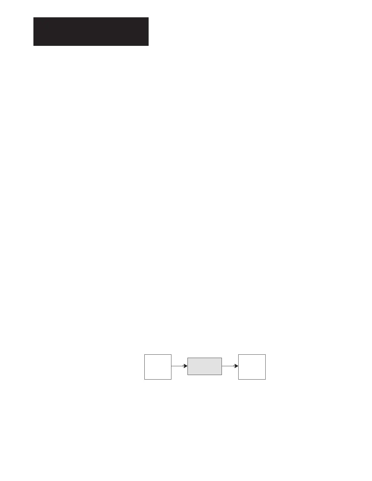
Drive Units – Specifies the Conversion Units as seen in the Drive.
Figure 5.1.
Drive Units Example
4096
Drive
Units
Drive Units
Conversion
Formula
1750
RPM
Engineering
Units
Factory Default – Parameter value as it will appear after the Drive
Initialize (Init) command has been sent from the Programming Terminal.
The Init values are the same as the default values listed in the Parameter
Descriptions section of this chapter.
Min – Minimum allowable value for the parameter. If no min value is
given, the parameter has not been assigned a minimum limit.
Max – Maximum allowable value for the parameter. If no max value is
given, the parameter has not been assigned a maximum limit.
Enum – Allows numbers or bits to be represented by text.

 Loading...


