Chapter 2
Installation/Wiring
2–37
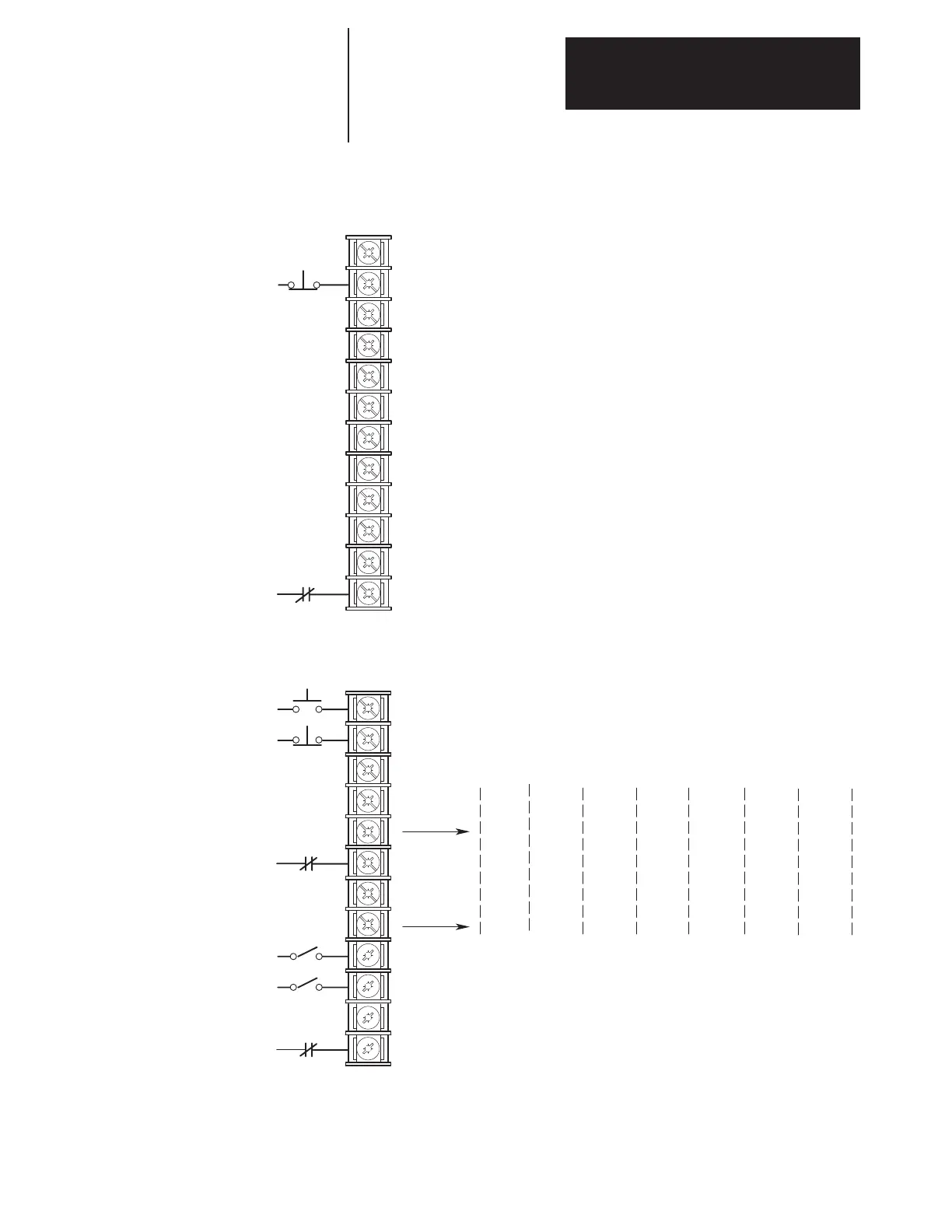
Figure 2.24.
Input Mode Selection & Typical TB3 Connections
19
20
21
22
23
24
25
26
27
28
29
30
Status
Not Stop/Clear Fault
3
Common
Status
Status
Status
Common
Status
Status
Status
Common
Enable
3
[Input Mode] 1
Factory Default
19
20
21
22
23
24
25
26
27
28
29
30
Start
Not Stop/Clear Fault
3,7,8
Common
Rev/Fwd
5
Auxiliary 3
Common
Speed Select 2
1
Speed Select 1
1
Common
Enable
3
Jog Stop
Type
2nd/1st
Accel
Digital
Pot Up
Speed
Select 3
1
Speed
Select 3
1
2nd/1st
Decel
Digital
Pot Dn
2 3 4 5,27
9
6
Mode
[Input Mode] 2–6, 17, 18
Three–Wire Control with Single–Source Reversing
1
See Speed Select Table on previous page.
2
Drive must be stopped to take Local Control.
Control by all other adapters is disabled (except Stop).
3
These inputs must be present before drive will start.
4
Bit 0 of [Direction Mask] must = 1 .
5
For Common Bus – Precharge Enable.
6
Bit 12 of Para 59 Logic Options must = 0 for Reverse Direction Control.
7
Soft Fault Reset Only, Must Cycle Power to Drive to Clear Hard Fault; Hard Fault = See Troubleshooting Section
8
Soft Fault Refer to Para 59 to Configure Start & Stop Type.
9 Digital Pot Value Zeroed When Stop Asserted.
Proc
Trim
Local
Control
2
Jog
Flux En
Jog
Ramp
Reset
17 18

 Loading...


