Chapter 2
Installation/Wiring
2–44
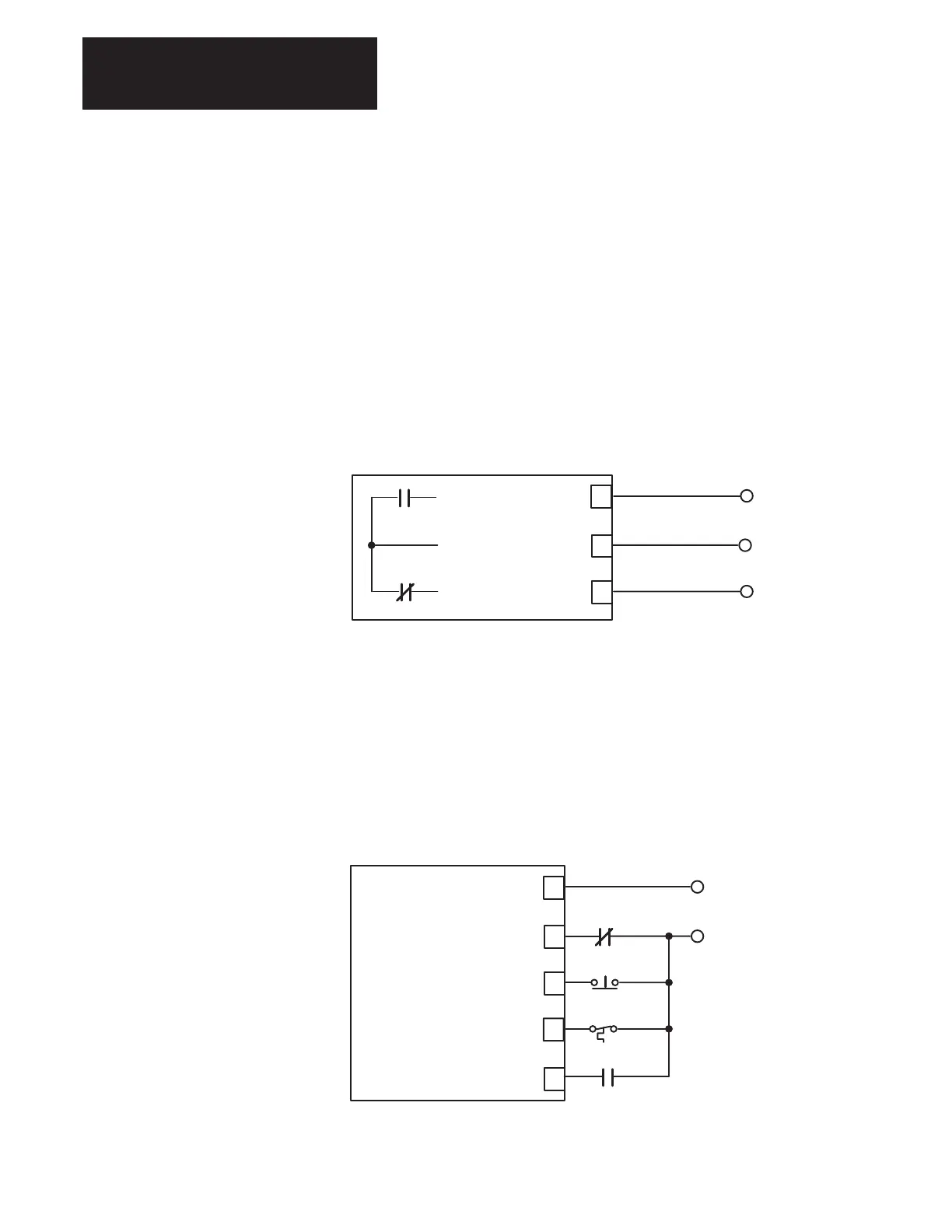
Discrete Outputs
Fault outputs from the 1336 FORCE are supplied at terminal block TB20
on the PLC Communication Adapter Board. Fault outputs provide warning
or fault signals based on drive programming.
Fault NC
Fault Com
Fault NO – A form C, NO /NC relay contact on the Standard Adapter
Board programmed to provide external warning or fault change–of–state
signals.
Contact Ratings = 2A @ 115 VAC
2A @ 30 VDC
Figure 2.31.
Typical Digital Output
Fault Com (Digital Out)
Fault NC (Digital Out)
10
9
8
TB20
Fault NO (Digital Out)
Discrete Inputs
Discrete Inputs to the 1336 FORCE are only supplied when a PLC
Communication Adapter Board is used. These inputs are supplied at
terminal block TB20.
Discrete inputs serve to enable and stop the Drive as well as provide
checks on drive and motor operation.
Figure 2.32.
Typical Digital Output
EXT FAULT (Digital Out)
INPUT COM (Digital Common)
NORM STOP (Digital In)
6
4
3
TB20
2
1
(Common)
MOTOR THERMO (Digital In)
DRIVE ENABLE (Digital In)
115V AC/+24V DC (HIGH)
EXTERNAL FAULT
STOP
MOTOR THERMO
ENABLE

 Loading...


