Chapter 2
Installation/Wiring
2–40
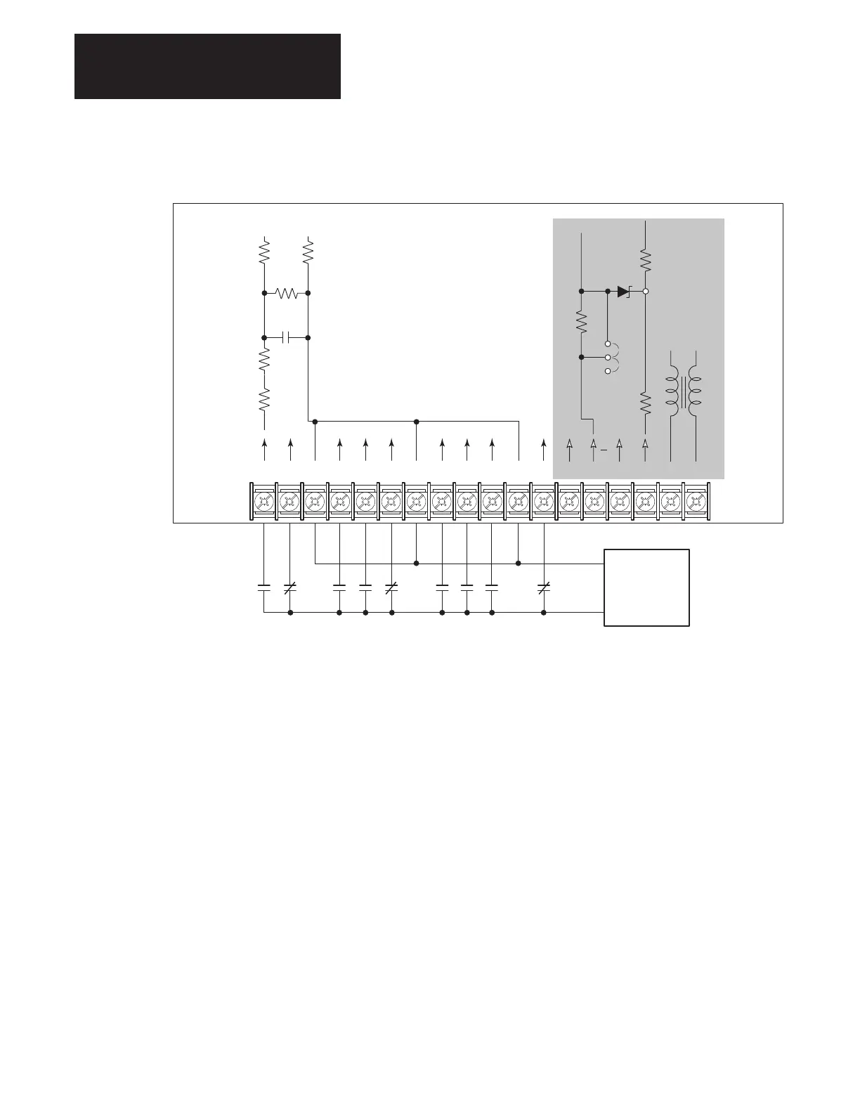
Figure 2.27.
Option L5/L5E Wiring
Typical
TB3
L5, L5E Options
AA
ENC
RET
ENC
12V
Common
+24V
Typical
12V
681
100
90.9
5V
JP4
19 20 21 22 23 24 25 26 27 28 29 30 31 32 33 34 35 36
0.22µf
1k
20k
510
510 510
User Supplied
24V AC/DC
Contacts shown are general, refer to Figures 2.24 & 2.25 for
Input Mode selection and recommended contact types.
NOT
USED
Option L5/L5E – 24V AC/DC Interface Board Requirements
Circuits used with Option L5/L5E must be capable of operating with high
= true logic.
DC external circuits in the low state must generate a voltage of no more
than 8V DC. Leakage current must be less than 1.5 mA into a 2.5k ohm
load.
AC external circuits in the low state must generate a voltage of no more
than 10V AC. Leakage current must be less than 2.5 mA into a 2.5k ohm
load.
Both AC and DC external circuits in the high state must generate a voltage
of +20 to +26 volts and source a current of approximately 10 mA for each
input.
The L5/L5E option is compatible with these Allen–Bradley PLC modules:
• 1771–OB • 1771–OQ16 • 1771–OB16
• 1771–OBD • 1771–OYL
• 1771–OBN • 1771–OZL
• 1771–OQ • 1771–OBB

 Loading...


