!
Chapter 2
Installation/Wiring
2–17
Power Cabling Input and output power connections are performed through terminal block
TB1 on the Gate Driver Board for Frame Size B (1–15 HP, 240V; 1–30 HP,
380V; 1–20 HP, 600V) drives. For larger horsepower drives (frame sizes
C,D,E,G and H), TB1 terminal blocks are located on the bottom of the
drive where both the input and output power connections are to be made.
Important: For maintenance and setup procedures, the drive may be
operated without a motor connected.
Table 2.B
TB1 Signals
Terminal Description
PE Power Earth Ground
R (L1), S (L2), T (L3) AC Line Input Terminals
+DC, –DC DC Bus Terminals
U (T1), V (T2), W (T3) Motor Connection
ATTENTION: The National Codes and standards (NEC, VDE,
BSA etc.) and local codes outline provisions for safely installing
electrical equipment. Installation must comply with specifica-
tions regarding wire types, conductor sizes, branch circuit
protection and disconnect devices. Failure to do so may result in
personal injury and/or equipment damage.
Motor Cables
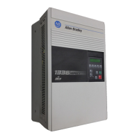
A variety of cable types are acceptable for use with the 1336 FORCE.
The choice of cable type is important to a successful application. Motor
cables must have an insulation thickness in excess of 15 mils. The THHN
type wire or any wire with a nylon coating is not recommended for
installations where there is a reasonable risk of wire damage (including
small nicks in coating or insulation) due to pulling through conduit or
where moisture is present. If wire integrity can be assured and no moisture
is present, THHN wire must have a minimum insulation thickness greater
than 15 mils, if conduit is used. Refer to page 2–18 under Conduit for
recommendations on the number of cables per conduit.
Refer to the Cable recommendations section in the Appendix of this
manual for additional information on specific cables.
Wire Size and Type Wire sizes must be selected individually, observing all applicable safety
and NEC and local regulations. Due to the drive overload capacity, the
conductors for the transformer primary and secondary must be sized (at a
minimum) for 125% of the maximum motor current. The motor
conductors must also be rated for 125% of the full load motor current. The
distance between the drive and motor may affect the size of the conductors
used.

 Loading...


