Chapter 2
Installation/Wiring
2–36
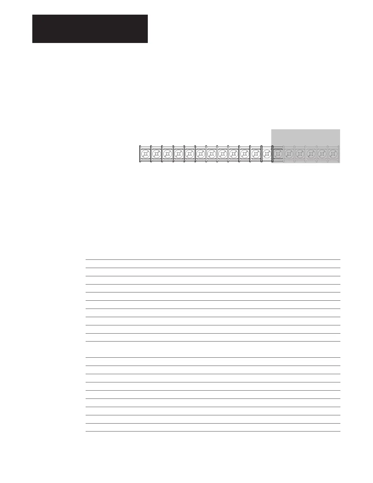
Figure 2.23 provides the terminal designations for TB3. The maximum and
minimum wire size accepted by TB3 is 2.1 and 0.30 mm
2
(14 and 22
AWG). Maximum torque for all terminals is 1.36 N–m (12 lb.–in.). Use
Copper wire only.
Figure 2.23.
TB3 Terminal Designations
NOTE: Terminals 31 thru 36 are not used with 1336 FORCE applications
19 20 21 22 23 24 25 26 27 28 29 30 31 32 33 34 35 36
Included on L4E, L5E & L6E Only
NOT USED
Input 1
Input 2 (Stop)
Common
Input 3
Input 4
Input 5
Common
Input 6
Input 7
Input 8
Common
Enable
Encoder B
Encoder NOT A
Encoder NOT B
Encoder A
+12V (200mA max.)
Encoder Common
The following table defines the input state of the Speed Select inputs for a
desired frequency source.
Table 2.E
Speed Select Input State vs. Frequency Source
Speed Select 3 Speed Select 2 Speed Select 1 Velocity Reference Source
TB3 Terminal 26 Terminal 27 Terminal 28 Interface Option (MOD L4,L5,L6)
O O O Ext Ref 1 Para 101*
O O X Preset Speed Ref 1 (P 119)
O X O Preset Speed Ref 2, (P 120)
O X X Preset Speed Ref 3, (P 121)
X O O Preset Speed Ref 4, (P 122)
X O X Preset Speed Ref 5, (P 123)
X X O External Reference 2 (P 104)
X X X Last State
Equivalent truth table implemented in Parameter 52 Logic Command Word
Para 52 Bit 14 Bit 13 Bit 12 Velocity Reference Source Bits
O O X Ext Ref 1 (P 101)
O X O Preset Speed Ref 1 (P 119)
O X X Preset Speed Ref 2 (P 120)
X O O Preset Speed Ref 3 (P 121)
X O X Preset Speed Ref 4 (P 122)
X X O Preset Speed Ref 5 (P 123)
X X X External Reference 2 (P 104)
O O O No Reference or Last State
0 = Open – input removed, X = Closed – input present
* Unless otherwise configured, this will default to the HIM speed reference input.

 Loading...


