Chapter 2
Installation/Wiring
2–39
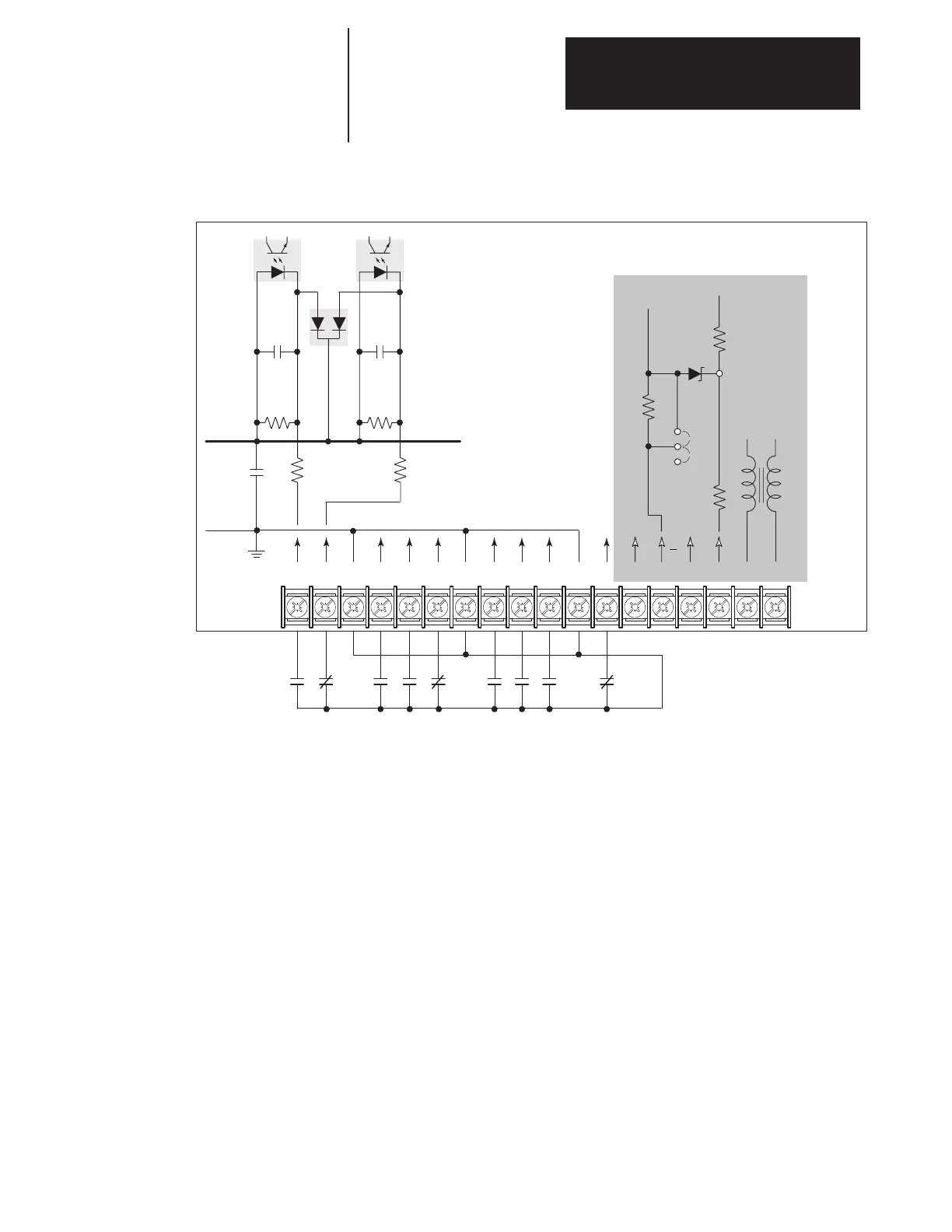
Figure 2.26.
Option L4/L4E Wiring
19 20 21 22 23 24 25 26 27 28 29 30 31 32
AA
ENC
RET
ENC
12V
33 34 35 36
Typical of Each Input
Typical
L4, L4E Options
Isolated
+5V
Isolated
Ground
0.1µf 0.1µf
0.1µf
10.7k
470 470
12V
681
100
90.9
5V
JP4
IGND
10.7k
Contacts shown are general, refer to Figure 2.24 for
Input Mode selection and recommended contact types.
TB3
NOT
USED
Option L4/L4E – Contact Closure Interface Board Requirements
Circuits used with Option L4/L4E must be capable of operating with low =
true logic. Reed type input devices are recommended.
In the low state, external circuits must be capable of a sinking current of
approximately 10mA to pull the terminal voltage low to 3.0V DC or less.
In the high state, external circuits must allow the terminal voltage to rise to
a voltage of 4.0–5.0V DC.
The L4/L4E option is compatible with the following Allen–Bradley PLC
modules:
• 1771–OYL
• 1771–OZL

 Loading...


