Chapter 2: Installation
32 2X-A Series Installation Manual
To determine noise immunity, check the communications error rate and the
stability of analogue values for installed devices.
Securing cables
Use 20 mm cable glands to ensure clean and secure connections. All cables
should be fed through the cable guides in the cabinet housing to eliminate
movement.
Overview of fire system connections
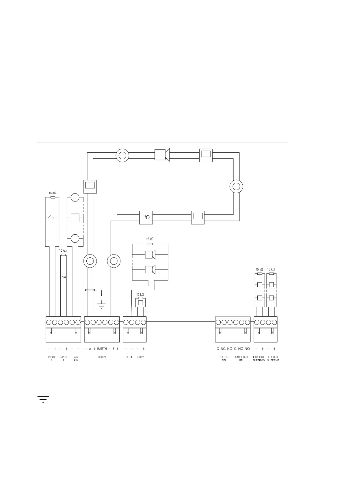
Figure 14: Overview of typical fire system connections with a single Class A loop
For input activation characteristics, see “Connecting inputs” on page 36.
Earth connection: Connect one side to the earth studs in the control panel cabinet (
the loop EARTH terminal), the other side can be left floating. See “Cabinet and PCB
layout” on page 19 for the location of the earth studs.
 Loading...