Chapter 2: Installation
2X-A Series Installation Manual 19
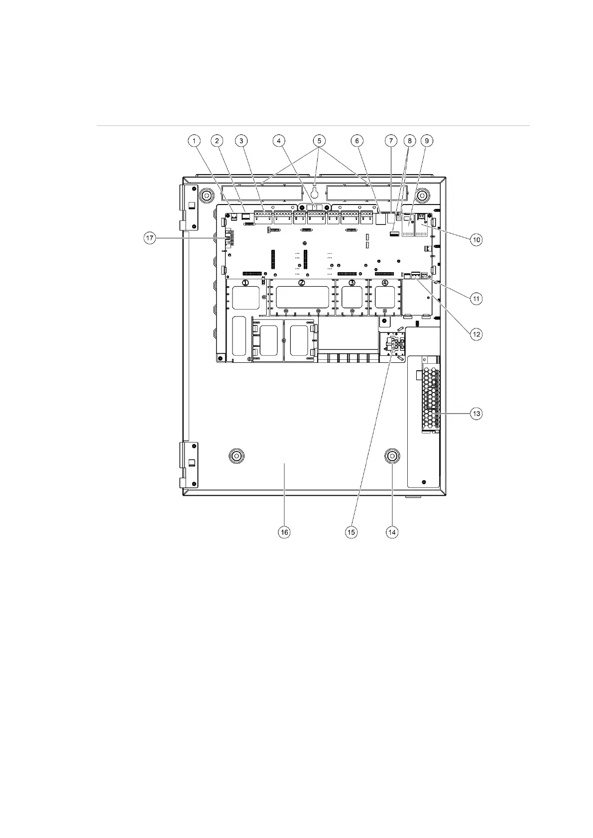
Cabinet and PCB layout
Figure 4: Large cabinet and PCB layout (with 6 A power supply)
. 24V connector
. COM2 serial port
. Loop and fire system connectors
. Spirit level
. Earth studs
. Ethernet connector
. USB type B connector
. USB type A connectors
9. COM0 serial port and interface connector
10. COM1 serial port and interface connector
11. Battery connector
12. Power supply connector
13. Power supply
14. Mounting holes
15. Mains terminal block and fuse
16. Battery area
17. User interface connector
 Loading...